Troubleshooting OSPF Route Advertisement
This section discusses the problems related with OSPF route advertisement. OSPF is a link-state protocol. When it forms neighbor relationships, it exchanges the entire link-state database with its neighbor(s). If any database information is not shared with the neighbor, the link-state characteristics of OSPF will break.
The most common reasons for OSPF to not share the database information about a specific link are as follows:
- The OSPF neighbor is not advertising routes.
- The OSPF neighbor (ABR) is not advertising the summary route.
- The OSPF neighbor is not advertising external routes.
- The OSPF neighbor is not advertising the default route.
The sections that follow address these problems, the possible causes for each, and the solutions for resolving them.
Problem: OSPF Neighbor Is Not Advertising Routes
When a neighbor doesn’t advertise a route, that route will not show up in the local router’s routing table. This means that the neighbor has not included the route in its database; otherwise, the local router must have received it.
The most common possible causes of this problem are as follows:
- OSPF is not enabled on the interface that is supposed to be advertised.
- The advertising interface is down.
- The secondary interface is in a different area than the primary interface.
Figure 9-45 shows an OSPF network setup used to produce this problem.

shows the output of show ip route 131.108.3.0, which indicates that the route is missing from the routing table of R2.
Example 9-118 R2’s Routing Table Is Missing Route 131.108.3.0
R2#show ip route 131.108.3.0
% Network not in table
R2#
OSPF Neighbor Is Not Advertising Routes—Cause: OSPF Not Enabled on the Interface That Is Supposed to Be Advertised
OSPF includes the interface subnet address in its database only if the OSPF is enabled on that interface. OSPF might not be enabled on an interface because of an incorrect network state-ment that doesn’t cover the IP address assigned on an interface or a missing network statement for that interface address. In both cases, OSPF will exclude the interface address from its data-base and will not advertise to its neighbor.
Figure 9-46 shows the flowchart to follow to solve this problem.

Debugs and Verification
Example 9-119 shows the output of show ip ospf database router for R1, which indicates that the network 131.108.3.0/24 is missing from the database.
Example 9-119 R1’s Database Is Missing 131.108.3.0
R1#show ip ospf database router 131.108.2.1
OSPF Router with ID (131.108.1.2) (Process ID 1)
Router Link States (Area 0)
LS age: 301
Options: (No TOS-capability, DC)
LS Type: Router Links
Link State ID: 131.108.2.1
Advertising Router: 131.108.2.1
LS Seq Number: 80000148
Checksum: 0x1672
Length: 48
Number of Links: 2
Link connected to: another Router (point-to-point)
(Link ID) Neighboring Router ID: 131.108.1.
(Link Data) Router Interface address: 131.108.1.1
Number of TOS metrics: 0
TOS 0 Metrics: 64
Link connected to: a Stub Network
(Link ID) Network/subnet number: 131.108.1.0
(Link Data) Network Mask: 255.255.255.0
Number of TOS metrics: 0
TOS 0 Metrics: 0
Link connected to: a Stub Network
(Link ID) Network/subnet number: 131.108.2.0
(Link Data) Network Mask: 255.255.255.0
Number of TOS metrics: 0
TOS 0 Metrics: 10
Example 9-120 shows the output of show ip ospf interface e0 on R1, which indicates that OSPF is not enabled on the interface. In Cisco IOS Software Release 12.0 and later, the output will not display anything if OSPF is not enabled on the interface.
Example 9-120 R1 Does Not Have OSPF Enabled on the Ethernet 0 Interface
R1#show ip ospf interface Ethernet 0
Ethernet0 is up, line protocol is up
OSPF not enabled on this interface
Example 9-121 shows the configuration of R1, which shows that the network statement for 131.108.3.0/24 is missing from the configuration.
Example 9-121 R1’s Configuration Is Missing a network Statement for 131.108.3.0
R1#
router ospf 1
network 131.108.1.0 0.0.0.255 area 0
network 131.108.2.0 0.0.0.255 area 0
Solution
R1 is not advertising its Ethernet 0 interface in its router LSA. The database output verifies that the Ethernet subnet is not being advertised.
The problem is that the network statement on R1 for the Ethernet interface is incorrect or the network statement is missing from the configuration. In this case, OSPF will not include that particular interface into the router LSA; when R2 receives the router LSA, this particular link is not included in it.
To solve this problem, make sure that the network statement is correct so that R1 includes 131.108.3.0/24 in its router LSA.
Example 9-122 shows that correct configuration that solves this problem.
Example 9-122 Correcting R1’s Configuration to Enable OSPF on 131.108.3.0/24
R1#
router ospf 1
network 131.108.1.0 0.0.0.255 area 0
network 131.108.2.0 0.0.0.255 area 0
network 131.108.3.0 0.0.0.255 area 0
Example 9-123 shows the router LSA of R1 after fixing this problem. The router LSA shows 131.108.3.0 now as a stub link.
Example 9-123 Network 131.108.3.0/24 Now Appears in the OSPF Database
1#show ip ospf database router 131.108.2.1
OSPF Router with ID (131.108.1.2) (Process ID 1)
Router Link States (Area 0)
LS age: 301
Options: (No TOS-capability, DC)
LS Type: Router Links
Link State ID: 131.108.2.1
Advertising Router: 131.108.2.1
LS Seq Number: 80000148
Checksum: 0x1672
Length: 48
Number of Links: 2
Link connected to: another Router (point-to-point)
(Link ID) Neighboring Router ID: 131.108.1.2
(Link Data) Router Interface address: 131.108.1.1
Number of TOS metrics: 0
TOS 0 Metrics: 64
Link connected to: a Stub Network
(Link ID) Network/subnet number: 131.108.1.0
(Link Data) Network Mask: 255.255.255.0
Number of TOS metrics: 0
TOS 0 Metrics: 0
R
Link connected to: a Stub Networ
(Link ID) Network/subnet number: 131.108.2.0
(Link Data) Network Mask: 255.255.255.0
Number of TOS metrics: 0
TOS 0 Metrics: 10
Link connected to: a Stub Network
(Link ID) Network/subnet number: 131.108.3.0
(Link Data) Network Mask: 255.255.255.0
Number of TOS metrics: 0
TOS 0 Metrics: 10
Example 9-124 shows the output of show ip route 131.108.3.0, which indicates that after fixing this problem, the route shows up in the routing table again.
Example 9-124 Verifying That the 131.108.3.0 Route Is Operational Again
R2#show ip route 131.108.3.0
Routing entry for 131.108.3.0/24
Known via "ospf 1", distance 110, metric 64, type intra area
Redistributing via ospf 1
Last update from 131.108.1.1 on Serial0, 04:22:21 ago
Routing Descriptor Blocks:
* 131.108.1.1, from 131.108.2.1, 04:22:21 ago, via Serial0
Route metric is 64, traffic share count is 1
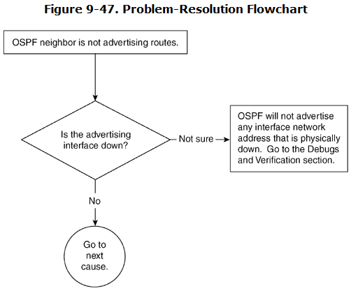
OSPF Neighbor Is Not Advertising Routes—Cause: Advertising Interface Is Down
OSPF does not advertise a network that is down. If an interface is down, the network assigned to that interface is not advertised in a router’s LSA.
Figure 9-47 shows the flowchart to follow to solve this problem.
Debugs and Verification
Recall from Figure 9-45 that the Ethernet 0 address is 131.108.3.0/24. If this interface is down, it will not be advertised in the OSPF database.
Example 9-125 shows the output of show ip ospf interface for Ethernet 0, which indicates that the line protocol is down.
Example 9-125 show ip ospf interface Command Output Determines Line Protocol Status of Ethernet 0 on R1
R1#show ospf interface Ethernet 0
Ethernet0 is up, line protocol is down
Internet Address 131.108.3.1/24, Area 0
Process ID 1, Router ID 131.108.2.1, Network Type BROADCAST, Cost: 10
Transmit Delay is 1 sec, State DOWN, Priority 1
No designated router on this network
No backup designated router on this network
Timer intervals configured, Hello 10, Dead 40, Wait 40, Retransmit 5
Example 9-126 shows that the Ethernet 0 network address of 131.108.3.0/24 is not listed in the router LSA of R1.
Example 9-126 R1’s Ethernet 0 Interface Is Missing from R1’s LSA
R2#show ip ospf database router 131.108.2.1
OSPF Router with ID (131.108.1.2) (Process ID 1)
Router Link States (Area 0)
LS age: 301
Options: (No TOS-capability, DC)
LS Type: Router Links
Link State ID: 131.108.2.1
Advertising Router: 131.108.2.1
LS Seq Number: 80000148
Checksum: 0x1672
Length: 48
Number of Links: 2
Link connected to: another Router (point-to-point)
(Link ID) Neighboring Router ID: 131.108.1.2
(Link Data) Router Interface address: 131.108.1.1
Number of TOS metrics: 0
TOS 0 Metrics: 64
Link connected to: a Stub Network
(Link ID) Network/subnet number: 131.108.1.0
(Link Data) Network Mask: 255.255.255.0
Number of TOS metrics: 0
TOS 0 Metrics: 0
Link connected to: a Stub Network
(Link ID) Network/subnet number: 131.108.2.0
(Link Data) Network Mask: 255.255.255.0
Number of TOS metrics: 0
TOS 0 Metrics: 10
Solution
To fix this problem, bring up the Ethernet 0 interface. Example 9-127 shows the interface statistics after fixing the Layer 2 problem. Some suggestions on fixing the Layer 2 problem were discussed earlier in this chapter in the section “OSPF Neighbor List Is Empty—Cause: Layer 1/2 Is Down.”
Example 9-127 Verifying That the Line Protocol Is Back Up for an Interface
R1#show ip ospf interface Ethernet 0
Ethernet0 is up, line protocol is up
Internet Address 131.108.3.1/24, Area 0
Process ID 1, Router ID 131.108.2.1, Network Type BROADCAST, Cost: 10
Example 9-128 shows the output of show ip route 131.108.3.0, which shows that after fixing this problem, the route came back in the routing table.
Example 9-128 Verifying That the 131.108.3.0 Route Is Operational Again
R2#show ip route 131.108.3.0
Routing entry for 131.108.3.0/24
Known via "ospf 1", distance 110, metric 64, type intra area
Redistributing via ospf 1
Last update from 131.108.1.1 on Serial0, 04:22:21 ago
Routing Descriptor Blocks:
* 131.108.1.1, from 131.108.2.1, 04:22:21 ago, via Serial0
Route metric is 64, traffic share count is 1
R2#
OSPF Neighbor Is Not Advertising Routes—Cause: Secondary Interface Is in a Different Area Than the Primary Interface
When dealing with secondary addresses, OSPF requires the secondary address to belong to the same area as the primary address. If this is not followed, OSPF will not advertise the secondary address in its router LSA.
Figure 9-48 shows the network setup used to produce this problem.

Figure 9-49 shows the flowchart to follow to solve this problem.

Debugs and Verification
Example 9-129 shows the router LSA information of R1. The LSA shows that 131.108.3.0/24 is not included in the database. R1 generates the router LSA for area 2, but because the second-ary address is the only address in area 2, the number of the link is 0. This is because the secondary interface address cannot be put into a separate area than the primary interface address.
Example 9-129 Displaying R1’s Router LSA Information
R1#show ip ospf database router 131.108.2.1
OSPF Router with ID (131.108.1.2) (Process ID 1)
Router Link States (Area 0)
LS age: 301
Options: (No TOS-capability, DC)
LS Type: Router Links
Link State ID: 131.108.2.1
Advertising Router: 131.108.2.1
LS Seq Number: 80000148
Checksum: 0x1672
Length: 48
Number of Links: 2
Link connected to: another Router (point-to-point)
(Link ID) Neighboring Router ID: 131.108.1.2
(Link Data) Router Interface address: 131.108.1.1
Number of TOS metrics: 0
TOS 0 Metrics: 64
Link connected to: a Stub Network
(Link ID) Network/subnet number: 131.108.1.0
(Link Data) Network Mask: 255.255.255.0
Number of TOS metrics: 0
TOS 0 Metrics: 0
Link connected to: a Stub Network
(Link ID) Network/subnet number: 131.108.2.0
(Link Data) Network Mask: 255.255.255.0
Number of TOS metrics: 0
TOS 0 Metrics: 10
Router Link States (Area 2)
LS age: 39
Options: (No TOS-capability, DC)
LS Type: Router Links
Link State ID: 131.108.2.1
Advertising Router: 131.108.2.1
LS Seq Number: 800001B0
Checksum: 0x46E4
Length: 24
Number of Links: 0
Example 9-130 shows the configuration of R1, which shows that the primary and secondary address are included in different areas.
Example 9-130 R1’s Primary and Secondary Address Configurations
R1#
interface Ethernet0
ip address 131.108.3.1 255.255.255.0 secondary
ip address 131.108.2.1 255.255.255.0
!
router ospf 1
network 131.108.1.0 0.0.0.255 area 0
network 131.108.2.0 0.0.0.255 area 0
network 131.108.3.0 0.0.0.255 area 2
Solution
To fix this problem, change the configuration on R1 so that the secondary address also belongs to area 0. Example 9-131 shows the configuration on R1, which shows that the secondary address is included in the area as the primary address.
Example 9-131 Configuring R1’s Secondary Address to Be in the Same Area as the Primary Address
R1#
interface Ethernet0
ip address 131.108.3.1 255.255.255.0 secondary
ip address 131.108.2.1 255.255.255.0
!
router ospf 1
network 131.108.1.0 0.0.0.255 area
network 131.108.2.0 0.0.0.255 area 0
network 131.108.3.0 0.0.0.255 area 0
Example 9-132 shows the output of show ip route 131.108.3.0, which shows that after fixing this problem, the route came back in the routing table.
Example 9-132 Verifying That the 131.108.3.0 Route Is Being Advertised Again
R2#show ip route 131.108.3.0
Routing entry for 131.108.3.0/24
Known via "ospf 1", distance 110, metric 64, type intra are
Redistributing via ospf 1
Last update from 131.108.1.1 on Serial0, 04:22:21 ago
Routing Descriptor Blocks:
* 131.108.1.1, from 131.108.2.1, 04:22:21 ago, via Serial0
Route metric is 64, traffic share count is 1
R2#
Problem: OSPF Neighbor (ABR) Not Advertising the Summary Route
When OSPF is configured with more than one area, one area has to be a backbone area. The router that sits at the border of the backbone and any other area is the ABR. The ABR generates the summary LSA for one area and sends it to another area. When the ABR fails to generate the summary LSA, the areas become isolated from each other.
The most common possible causes of this problem are as follows:
- An area is configured as a totally stubby area.
- An ABR is not connected to area 0.
- A discontiguous area 0 exists.
OSPF Neighbor (ABR) Not Advertising the Summary Route—Cause: Area Is Configured as Totally Stubby Area
When an area is configured as a stubby area, no external LSA can be leaked into that area. Similarly, an area can be configured as a totally stubby area, which means that no external or summary LSAs can be leaked into this area.
Figure 9-50 shows an OSPF network setup used to produce this problem. R1 is an ABR, and area 2 is defined as a totally stubby area.

Figure 9-51 shows the flowchart to follow to solve this problem.

Debugs and Verification
Example 9-133 shows the configuration of R1 that shows area 2 configured as a totally stubby area.
Example 9-133 R1 Configuration Shows Area Types
R1#
router ospf 1
network 131.108.1.0 0.0.0.255 area 2
network 131.108.2.0 0.0.0.255 area 3
network 131.108.3.0 0.0.0.255 area 0
area 2 stub no-summary
Example 9-134 shows the output of show ip ospf database summary for 131.108.2.0, which indicates that the summary LSA is generated only in area 0 and not in area 2.
Example 9-134 show ip ospf database summary Command Output Shows Summary LSA Information
R1#show ospf database summary 131.108.2.0
OSPF Router with ID (131.108.3.1) (Process ID 1)
Summary Net Link States (Area 0)
LS age: 58
Options: (No TOS-capability, DC)
LS Type: Summary Links(Network)
Link State ID: 131.108.2.0 (summary Network Number)
Advertising Router: 131.108.3.1
LS Seq Number: 8000000E
Checksum: 0x4042
Length: 28
Network Mask: /24
TOS: 0 Metric: 1
Solution
In this example, area 2 is configured as a totally stubby area, so no summary LSA is originated for this area by the ABR.
If there is only a single exit point, there is no need to receive specific summary LSAs in an area; the default summary LSA of 0.0.0.0 is sufficient. This is also true in the case of a totally stubby NSSA area.
Because this is normal behavior, no solution is given for this. However, if multiple ABRs exist for this area and receiving a specific summary LSA is necessary to avoid suboptimal routing, just remove the no-summary keyword from the area 2 configuration on ABR. This will make area 2 a stub and all the summary LSAs will be leaked into this area.
OSPF Neighbor (ABR) Not Advertising the Summary Route—Cause: ABR Is Not Connected to Area 0
When a router is connected to more than one area, one of those areas must be area 0. The ABR will not generate summary LSAs if it is not connected to area 0. This is standard OSPF behavior.
Figure 9-52 shows an OSPF network experiencing this problem. R1 is between area 2 and area 3, but it is not connected to area 0.

Figure 9-53 shows the flowchart to follow to solve this problem.

Debugs and Verification
Example 9-135 shows that R1 is not originating a summary.
Example 9-135 R1 Is Not Originating a Summary Route
R1#show ip ospf database summary
OSPF Router with ID (131.108.3.1) (Process ID 1)
R1#
Example 9-136 shows the configuration on R1, which shows that R1 is not connected to area 0.
Example 9-136 R1’s Configuration Indicates That It Is Not Connected to Area 0
router R1#
router ospf 1
network 131.108.1.0 0.0.0.255 area 2
network 131.108.3.0 0.0.0.255 area 3
There is another way to see whether an area is connected to the backbone. Example 9-137 shows the output of show ip ospf. If this router were connected to area 0, the output would say “It is an area border router.”
Example 9-137 show ip ospf Command Output Indicates Whether the Router Is an ABR
R1#show ip ospf
Routing Process "ospf 1" with ID 131.108.3.
Supports only single TOS(TOS0) routes
SPF schedule delay 5 secs, Hold time between two SPFs 10 secs
Minimum LSA interval 5 secs. Minimum LSA arrival 1 secs
Solution
To solve this problem, create a backbone area. After a backbone area is created on R1, it will start generating summary LSAs.
If no area 0 exists in the network, one of the areas must be changed to area 0 for OSPF to work properly.
Example 9-138 shows the new configuration, which shows that R1 now is connected to area 0 by removing 131.108.3.0 from area 3 and putting it into area 0.
Example 9-138 Configuring R1 to Connect to Area 0
R1#
router ospf 1
network 131.108.1.0 0.0.0.255 area 2
network 131.108.3.0 0.0.0.255 area 0
If a backbone area already exists, create a virtual link between the nearest ABR and R1, as shown in Example 9-139.
Example 9-139 Creating a Virtual Link Between R1 and the Nearest ABR
R1#
router ospf 1
network 131.108.1.0 0.0.0.255 area 2
network 131.108.3.0 0.0.0.255 area 3
area 2 virtual-link 141.108.1.1
Example 9-140 shows the output of show ip ospf, which now shows R1 as an ABR.
Example 9-140 Verifying That R1 Is an ABR
R1#show ip ospf
Routing Process "ospf 1" with ID 131.108.3.1
Supports only single TOS(TOS0) routes
It is an area border router
SPF schedule delay 5 secs, Hold time between two SPFs 10 secs
Minimum LSA interval 5 secs. Minimum LSA arrival 1 secs
Example 9-141 shows that R1 starts generating the summary LSA.
Example 9-141 Verifying That R1 Is Generating a Summary LSA
R1#show ip ospf database summary
OSPF Router with ID (131.108.3.1) (Process ID 1)
Summary Net Link States (Area 0)
LS age: 58
Options: (No TOS-capability, DC)
LS Type: Summary Links(Network)
Link State ID: 131.108.1.0 (summary Network Number)
Advertising Router: 131.108.3.1
LS Seq Number: 8000000E
Checksum: 0x4042
Length: 28
Network Mask: /24
TOS: 0 Metric: 1
Summary Net Link States (Area 2)
LS age: 58
Options: (No TOS-capability, DC)
LS Type: Summary Links(Network)
Link State ID: 131.108.3.0 (summary Network Number)
Advertising Router: 131.108.3.1
LS Seq Number: 8000000E
Checksum: 0x4042
Length: 28
Network Mask: /24
TOS: 0 Metric: 1
OSPF Neighbor (ABR) Not Advertising the Summary Route—Cause: Discontiguous Area 0
Figure 9-54 shows an OSPF network experiencing this problem. The link between R1 and R2 is broken, which makes area 0 discontiguous.

Figure 9-55 shows the flowchart to follow to solve this problem.

Debugs and Verification
Example 9-142 shows the routing table of ABR 2. The route 131.108.1.0/24 shows up in the routing table as an interarea route. The route 131.108.1.0 truly exists in the backbone area, but because the backbone has become discontiguous, this route is coming to ABR 2 through area 2 as an interarea route. The ABR 2 will not generate the summary LSA for this route because it’s an interarea route.
Example 9-142 ABR 2 Is Receiving the 131.108.1.0/24 Route as an Interarea Route Because of a Discontiguous Backbone
ABR2#show ip route 131.108.1.0
Routing entry for 131.108.1.0/24
Known via "ospf 1", distance 110, metric 129, type inter area
Redistributing via ospf 1
Last update from 131.108.0.1 on Serial0.1, 00:56:02 ag
Routing Descriptor Blocks:
* 131.108.0.1, from 131.108.3.1, 00:56:02 ago, via Serial0.1
Route metric is 129, traffic share count is 1
Example 9-143 shows that ABR 2 is not generating a summary LSA for this route into area 0.
Example 9-143 No Summary LSA Is Generated for 131.108.1.0 into Area 0
ABR2#show ip ospf database summary 131.108.1.0
OSPF Router with ID (131.108.4.1) (Process ID 1)
ABR2#
Solution
This is obviously a bad design. The backbones are attached to each other through one link. If that link fails, the backbone becomes discontiguous. ABR 2 receives the interarea route from ABR 1 and doesn’t create summary LSAs for those routes. This is in accordance with OSPF RFC 2328 that a summary LSA should not be injected into the backbone for interarea routes.
Injecting a summary LSA into the backbone for interarea routers isolates the backbones from each other. To fix this problem, be sure to avoid a single point of failure, as shown in this example, that could make a backbone area discontiguous. Another solution is to create a virtual link between ABR 1 and ABR 2. After creating the virtual link, the area 0 database of ABR 1 and ABR 2 will be synchronized over the virtual link. It will look exactly as if there were a physical link between ABR 1 and ABR 2 and that link were in area 0. The only difference is that both ABR 1 and ABR 2 would use area 2 to forward the OSPF packets. For more infor-mation on virtual links, refer back to Chapter 8.
Example 9-144 shows the configuration of both ABR 1 and ABR 2, which shows that a virtual link is configured to make area 0 contiguous.
Example 9-144 Configuring ABR 1 and ABR 2 with a Virtual Link
ABR1#
router ospf 1
network 131.108.0.0 0.0.0.255 area 2
network 131.108.3.0 0.0.0.255 area 0
area 2 virtual-link 131.108.4.1
_____________________________________________________________________________________
ABR2#
router ospf 1
network 131.108.0.0 0.0.0.255 area 2
network 131.108.4.0 0.0.0.255 area 0
area 2 virtual-link 131.108.3.1
A virtual link is configured first by defining the transit area. This is the area that is common between the two ABRs. This area is used to form a virtual adjacency between the two ABRs. In this example, it is area 2. On ABR 1, the command defined under router OSPF is area 2 virtual-link 131.108.4.1. The address 131.108.4.1 is the router ID of ABR 2. Similarly, the address 131.108.3.1 is the router ID of ABR 1. The router ID is the highest IP address on the box—or, if a loopback exists, the loopback becomes the router ID. It is highly recommended that you define a loopback address so that it will be elected as a router ID. One good reason is that, if a link is elected as a router ID instead of a loopback and that link goes down, the router ID will be changed. When a router ID changes, it breaks the virtual link also. On the other hand, if a loopback is defined as a router ID, the router ID always will be the same.
Example 9-145 shows that after creating the virtual link, ABR 2 starts receiving router LSAs for area 0 that include this link 131.108.1.0/24.
Example 9-145 Verifying That ABR 2 Receives Router LSAs for Area 0, Including the 131.108.1.0/24 Link
ABR2#show ip ospf database router 131.108.1.1
OSPF Router with ID (131.108.3.1) (Process ID 1)
Router Link States (Area 0)
Routing Bit Set on this LSA
LS age: 6 (DoNotAge)
Options: (No TOS-capability, DC)
LS Type: Router Links
Link State ID: 131.108.1.1
Advertising Router: 131.108.1.1
LS Seq Number: 80000002
Checksum: 0xC375
Length: 48
Number of Links: 3
Link connected to: a point-to-point Link
(Link ID) Neighboring Router ID: 131.108.3.1
(Link Data) Router Interface address: 131.108.3.2
Number of TOS metrics: 0
TOS 0 Metrics: 64
Link connected to: a Stub Network
(Link ID) Network/subnet number: 131.108.3.0
(Link Data) Network Mask: 255.255.255.0
Number of TOS metrics: 0
TOS 0 Metrics: 1
Link connected to: a Stub Network
(Link ID) Network/subnet number: 131.108.1.0
(Link Data) Network Mask: 255.255.255.0
Number of TOS metrics: 0
TOS 0 Metrics: 1
Example 9-146 shows that R2 starts receiving intra-area routes for 131.108.1.0/24 after the virtual link is created.
Example 9-146 Verifying That R2 Receives Intra-Area Routes for 131.108.1.0/24
ABR2#show ip route 131.108.1.0
Routing entry for 131.108.1.0/24
Known via "ospf 1", distance 110, metric 193,type intra area
Redistributing via ospf 1
Last update from 131.108.4.1 on Serial0.1, 00:56:02 ago
Routing Descriptor Blocks:
* 131.108.4.1, from 131.108.4.1, 00:56:02 ago, via Serial0.1
Route metric is 193, traffic share count is 1
Problem: OSPF Neighbor Is Not Advertising External Routes
Whenever there is a redistribution in OSPF, it generates an external LSA (Type 5) that is flooded throughout the OSPF network. External LSAs are not leaked into stub, totally stubby, and NSSA areas.
The most common possible causes of this problem are as follows:
- The area is configured as a stub or NSSA.
- The NSSA ABR is not translating Type 7 into Type 5 LSA.
OSPF Neighbor Is Not Advertising External Routes—Cause: Area Is Configured as a Stub Area or NSSA
In OSPF, Type 5 LSAs are not allowed in a stub or NSSA area. When entering the redistribute command on a router that is completely in a stub or NSSA area, a warning message is displayed. This redistribute command in the configuration is incapable of importing any external LSAs into a stub or NSSA area.
Figure 9-56 shows the flowchart to follow to solve this problem.

Debugs and Verification
Example 9-147 shows the configuration error when trying to redistribute into OSPF from another routing protocol on a router in a stub area.
Example 9-147 Errors Caused by Redistributing into OSPF on a Stub Area Router
R1(config)#router ospf 1
R1(config-router)#redistribute rip subnets
Warning: Router is currently an ASBR while having only one area which is a stub area
Example 9-148 shows the configuration on R1. Even though RIP is being redistributed, R1 will not generate Type 5 LSAs for RIP subnets because R1 is completely in a stub area. For more information on Type 5 LSAs, refer to Chapter 8.
Example 9-148 Redistributing RIP into OSPF While an OSPF Area Is Defined as a Stub
R1#
router ospf 1
redistribute rip subnets
network 131.108.1.0 0.0.0.255 area 2
network 131.108.2.0 0.0.0.255 area 2
area 2 stub
Example 9-149 shows that no external LSAs are generated by R1 because R1 is completely in a stub area. R1 will ignore the redistribution command.
Example 9-149 No External LSAs Are Generated by R1
R1#show ip ospf database external 132.108.3.0
OSPF Router with ID (131.108.2.1) (Process ID 1)
R1#
Solution
This problem can be solved in two ways. One solution is to make area 2 a normal area by taking out the area 2 stub command on all the routers in area 2. This is not a good solution because sometimes, a stub area does not require external LSAs.
The second solution is a preferred solution that involves changing the entire area as an NSSA. An NSSA permits redistribution of external routes. However, the NSSA will not generate Type 5 LSAs. It will generate Type 7 LSAs, which will be converted to Type 5 LSAs by the NSSA ABR. Chapter 8 explains NSSAs in more detail.
Example 9-150 shows the configuration that converts a stub area into an NSSA. The area id nssa command must be issued on all routers in the NSSA.
Example 9-150 Converting a Stub Area to an NSSA to Permit Redistribution of External Routes
R1#
router ospf 1
redistribute rip subnets
network 131.108.1.0 0.0.0.255 area 2
network 131.108.2.0 0.0.0.255 area 2
area 2 nssa
Example 9-151 shows that R1 is generating Type 7 LSAs for two RIP routes into the NSSA area. The NSSA ABR converts these Type 7 LSAs further into Type 5 LSAs, which then can be flooded to the rest of the OSPF domain.
Example 9-151 Showing OSPF Generating Type 7 LSAs for RIP Routes
R1#show ip ospf database nssa-external 132.108.3.0
OSPF Router with ID (131.108.2.1) (Process ID 1)
Type-7 AS External Link States (Area 2)
LS age: 1161
Options: (No TOS-capability, Type 7/5 translation, DC)
LS Type: AS External Link
Link State ID: 132.108.3.0 (External Network Number )
Advertising Router: 131.108.2.1
LS Seq Number: 80000001
Checksum: 0x550
Length: 36
Network Mask: /24
Metric Type: 2 (Larger than any link state path)
TOS: 0
Metric: 1
Forward Address: 0.0.0.0
External Route Tag: 1
R1#
R1#show ip ospf database nssa-external 132.108.4.0
OSPF Router with ID (131.108.2.1) (Process ID 1)
Type-7 AS External Link States (Area 2)
LS age: 1161
Options: (No TOS-capability, Type 7/5 translation, DC)
LS Type: AS External Link
Link State ID: 132.108.4.0 (External Network Number )
Advertising Router: 131.108.2.1
LS Seq Number: 80000001
Checksum: 0x550
Length: 36
Network Mask: /24
Metric Type: 2 (Larger than any link state path)
TOS: 0
Metric: 1
Forward Address: 0.0.0.0
External Route Tag: 1
R1#
OSPF Neighbor Is Not Advertising External Routes—Cause: NSSA ABR Not Translating Type 7 LSAs into Type 5 LSAs
NSSA RFC 1587 states that before NSSA ABR converts from Type 7 into Type 5, all NSSA ABRs must examine all NSSA ABRs for a particular NSSA. The ABR with the highest router ID must do the conversion of Type 7 into Type 5. If Type 7 is not translated into Type 5 by the NSSA ABR, no routers outside of NSSA become aware of the external route redistribution that is happening within the NSSA. This defeats the entire purpose of NSSA.
Figure 9-57 shows an OSPF network experiencing this problem. Router 2 is an NSSA ABR, but it’s not converting Type 7 LSAs into Type 5 LSAs.

Figure 9-58 shows the flowchart to follow to solve this problem.

Debugs and Verification
Example 9-152 shows the output of show ip ospf database nssa-external on route 132.108.4.0, indicating that R2 is generating Type 7 LSAs.
Example 9-152 show ip ospf database nssa-external Command Output Indicates That Type 7 Is Being Generated
R2#show ip ospf database nssa-external 132.108.4.0
OSPF Router with ID (131.108.1.2) (Process ID 1)
Type-7 AS External Link States (Area 2)
LS age: 1161
Options: (No TOS-capability, Type 7/5 translation, DC)
LS Type: AS External Link
Link State ID: 132.108.4.0 (External Network Number )
Advertising Router: 131.108.1.2
LS Seq Number: 80000001
Checksum: 0x550
Length: 36
Network Mask: /24
Metric Type: 2 (Larger than any link state path)
TOS: 0
Metric: 1
Forward Address: 0.0.0.0
External Route Tag: 1
Example 9-153 shows the output of the show ip ospf database external command for 132.108.4.0, which indicates that R2 is not converting Type 7 LSAs into Type 5 LSAs.
Example 9-153 show ip ospf database external Command Output Indicates That Conversion of Type 7 to Type 5 Is Not Occurring
R2#show ip ospf database external 132.108.4.0
OSPF Router with ID (131.1081.2) (Process ID 1)
R2#
Example 9-154 shows that R2 is an NSSA ABR, so it is supposed to do the conversion.
Example 9-154 Verifying That R2 Is an NSSA ABR, Subject to Type 7-to-Type 5 LSA Conversion
R2#show ip ospf
Routing Process "ospf 1" with ID 131.108.1.2
Supports only single TOS(TOS0) routes
It is an area border router
SPF schedule delay 5 secs, Hold time between two SPFs 10 secs
Minimum LSA interval 5 secs. Minimum LSA arrival 1 secs
Number of external LSA 3. Checksum Sum 0x14DAA
Number of DCbitless external LSA 0
Number of DoNotAge external LSA 0
Number of areas in this router is 4. 3 normal 0 stub 1 nssa
Area BACKBONE(0)
Number of interfaces in this area is 2
Area has no authentication
SPF algorithm executed 60 times
Area ranges are
Number of LSA 16. Checksum Sum 0x9360D
Number of DCbitless LSA 7
Number of indication LSA 0
Number of DoNotAge LSA 0
Area 2
Number of interfaces in this area is 1
It is a NSSA area
Perform type-7/type-5 LSA translation
Area has no authentication
SPF algorithm executed 54 times
Area ranges are
Number of LSA 11. Checksum Sum 0x7A449
Number of DCbitless LSA 0
Number of indication LSA 0
Number of DoNotAge LSA 0
Example 9-155 shows another router in the NSSA area, R1, which also claims to be an ABR. This router is a fake ABR because it is not connected to area 0.
Example 9-155 show ip ospf Command Output Indicates That R1 Claims to Be an ABR
R1#show ip ospf
Routing Process "ospf 1" with ID 131.108.2.1
Supports only single TOS(TOS0) routes
It is an area border router
Summary Link update interval is 00:30:00 and the update due in 00:29:48
External Link update interval is 00:30:00 and the update due in 00:19:43
SPF schedule delay 5 secs, Hold time between two SPFs 10 secs
Number of DCbitless external LSA 0
Number of DoNotAge external LSA 0
Number of areas in this router is 2. 1 normal 0 stub 1 nssa
Area BACKBONE(0) (Inactive)
Number of interfaces in this area is 1
Area has no authentication
SPF algorithm executed 2 times
Area ranges are
Link State Update Interval is 00:30:00 and due in 00:29:47
Link State Age Interval is 00:20:00 and due in 00:19:47
Number of DCbitless LSA 0
Number of indication LSA 0
Number of DoNotAge LSA 0
Area 2
Number of interfaces in this area is 1
It is a NSSA area
Area has no authentication
SPF algorithm executed 65 times
Area ranges are
Link State Update Interval is 00:30:00 and due in 00:16:27
Link State Age Interval is 00:20:00 and due in 00:14:39
Number of DCbitless LSA 0
Number of indication LSA 0
Number of DoNotAge LSA 0
Example 9-156 shows that R1 is doing all the conversion instead of R2.
Example 9-156 R1 Performs Type 7-to-Type 5 LSA Conversion Instead of R2
R1#show ip ospf database external 132.108.3.0
OSPF Router with ID (131.108.2.1) (Process ID 1)
Type-5 AS External Link States
LS age: 1161
Options: (No TOS-capability, DC)
LS Type: AS External Link
Link State ID: 132.108.3.0 (External Network Number )
Advertising Router: 131.108.2.1
LS Seq Number: 80000001
Checksum: 0x550
Length: 36
Network Mask: /24
Metric Type: 2 (Larger than any link state path)
TOS: 0
Metric: 1
Forward Address: 0.0.0.0
External Route Tag: 1
R1#
R1#show ip ospf database external 132.108.4.0
OSPF Router with ID (131.108.2.1) (Process ID 1)
Type-5 AS External Link States
LS age: 1161
Options: (No TOS-capability, DC)
LS Type: AS External Link
Link State ID: 132.108.4.0 (External Network Number )
Advertising Router: 131.108.2.1
LS Seq Number: 80000001
Checksum: 0x550
Length: 36
Network Mask: /24
Metric Type: 2 (Larger than any link state path)
TOS: 0
Metric: 1
Forward Address: 0.0.0.0
External Route Tag: 1
R1#
Example 9-157 shows the OSPF configuration on R1. A network statement on R1 includes one interface of R1 in area 0. This network statement is causing problems because none of the inter-faces on R1 belongs to the backbone.
Example 9-157 R1’s Configuration Shows One Interface in Area 0
R1#
router ospf 1
network 131.108.1.0 0.0.0.255 area 2
network 131.108.2.0 0.0.0.255 area 2
network 131.108.5.0 0.0.0.255 area 0
area 2 nssa
Solution
In this case, R1 has a router ID (RID) of 131.108.2.1 and R2 has a router ID of 131.108.1.2, as shown in the output of Examples 9-154 and 9-155. Because R1 has a higher RID than R2, R1 does the conversion and the Type 5 LSA goes into a black hole.
You can resolve this problem using multiple solutions:
- Remove the wrong network statement.
- Change the router ID of R1 so that it is lower than R2’s.
- Change the router ID of R2 so that it is higher than R1’s.
Example 9-158 shows the easiest solution, which is to remove the incorrect network statement.
Example 9-158 Correcting the network Statement on R1 so That R2 Performs the Type 7-to-Type 5 LSA Conversion
R1#
router ospf 1
network 131.108.1.0 0.0.0.255 area 2
network 131.108.2.0 0.0.0.255 area 2
no network 131.108.5.0 0.0.0.255 area 0
area 2 nssa
The other solution is to alter the router ID of R1 or R2 so that either R1’s is lower than R2’s or R2’s is higher than R1’s. To change the router ID, configure the loopback interface of R1 with a lower IP address than R2’s loopback, and then restart the OSPF process. Restarting OSPF will cause network downtime for few seconds. The faster you enter the OSPF configu-ration back on the router, the less downtime there will be. In Cisco IOS Software Release 12.0 and later, a command has been added to configure the router ID manually and then restart OSPF. Example 9-159 shows how to change the router ID with Cisco IOS Software Release 12.0.
Example 9-159 Changing the Router ID of R1 to Be Lower Than R2’s
R2(config)#router ospf 1
R2(config-router)#router-id 131.108.0.1
R2(config-router)#end
R2#clear ip ospf process
Example 9-160 shows that after fixing the configuration, R2 starts converting Type 7 LSAs into Type 5 LSAs properly. The output of show ip ospf database external on R2 shows that it is generating Type 5 LSAs and that R1 is receiving Type 5 LSAs.
Example 9-160 Confirming That the LSA Type Conversion Problem Has Been Resolved
R2#show ip ospf database external 132.108.3.0
OSPF Router with ID (131.108.1.2) (Process ID 1)
+
Type-5 AS External Link States
LS age: 1161
Options: (No TOS-capability, DC)
LS Type: AS External Link
Link State ID: 132.108.3.0 (External Network Number )
Advertising Router: 131.108.1.2
LS Seq Number: 80000001
Checksum: 0x550
Length: 36
Network Mask: /24
Metric Type: 2 (Larger than any link state path)
TOS: 0
Metric: 1
Forward Address: 0.0.0.0
External Route Tag: 1
R1#
R1#show ip ospf database external 132.108.4.0
OSPF Router with ID (131.108.1.2) (Process ID 1)
Type-5 AS External Link States
LS age: 1161
Options: (No TOS-capability, DC)
LS Type: AS External Link
Link State ID: 132.108.4.0 (External Network Number )
Advertising Router: 131.108.1.2
LS Seq Number: 80000001
Checksum: 0x550
Length: 3
Network Mask: /2
Metric Type: 2 (Larger than any link state path)
TOS: 0
Metric: 1
Forward Address: 0.0.0.0
External Route Tag: 1
R1#
Problem: OSPF Neighbor Not Advertising Default Routes
Sometimes, OSPF uses a default route for destinations that are unknown to OSPF. Most of the time, these destinations are networks external to OSPF. Instead of importing all the external routes into OSPF, just one default route is needed that will be used for all unknown external destinations. In the absence of such a default route, all the traffic destined for any unknown address will be dropped by OSPF.
The most common possible causes for an OSPF router not to advertise the default route are as follows:
- The default-information originate command is missing.
- The default route is missing from the neighbor’s routing table.
- A neighbor is trying to originate a default into a stub area.
- The NSSA ABR/ASBR is not originating the Type 7 default.
OSPF Neighbor Not Advertising Default Routes—Cause: Missing default-information originate Commands
OSPF does not originate the default route unless the OSPF default-information originate command is present in the OSPF configuration. This command originates the default route on the router on which it is configured. There is no other way in OSPF to generate the default route. Figure 9-59 shows a network setup that produces this problem.

Figure 9-60 shows the flowchart to follow to solve this problem.

Debugs and Verification
Example 9-161 shows that R1 is receiving a default route through RIP. This is important because if R1, which is the originator of a default route, does not have the default route, it can’t generate a default route in OSPF.
Example 9-161 R1 Receives a Default Route Through RIP
R1#show ip route 0.0.0.0
Routing entry for 0.0.0.0/0, supernet
Known via "rip", distance 120, metric 1, candidate default path
Redistributing via rip
Last update from 132.108.0.2 on Serial0, 00:00:16 ago
Routing Descriptor Blocks:
132.108.0.2, from 132.108.0.2, 00:00:16 ago, via Serial0
Route metric is 1, traffic share count is 1
Example 9-162 shows the configuration of R1 illustrating that R1 is redistributing all the RIP routes into OSPF. As mentioned in the beginning of this problem, the only way to originate a default in OSPF is through the default-information originate command. So, redistribution of a default route will not cause OSPF to generate the default route.
Example 9-162 R1 Redistributes All RIP Routes into OSPF
R1#
router ospf 1
redistribute rip subnets
network 131.108.1.0 0.0.0.255 area 0
network 131.108.2.0 0.0.0.255 area 0
router rip
network 132.108.0.0
!
Example 9-163 shows that 0.0.0.0 is not in R1’s database but that other RIP routes are in the database. This indicates that the default route that was a part of RIP did not get redistributed into OSPF.
Example 9-163 R1’s OSPF Database Is Missing Information About the 0.0.0.0 Route
R1#show ip ospf database external 0.0.0.0
OSPF Router with ID (131.108.2.1) (Process ID 1)
R1#
R1#show ip ospf database external 132.108.3.0
OSPF Router with ID (131.108.2.1) (Process ID 1)
Type-5 AS External Link States
LS age: 1161
Options: (No TOS-capability, DC)
LS Type: AS External Link
Link State ID: 132.108.3.0 (External Network Number )
Advertising Router: 131.108.2.1
LS Seq Number: 80000001
Checksum: 0x550
Length: 36
Network Mask: /24
Metric Type: 2 (Larger than any link state path)
TOS: 0
Metric: 1
Forward Address: 0.0.0.0
External Route Tag: 1
R1#
R1#show ip ospf database external 132.108.4.0
OSPF Router with ID (131.108.2.1) (Process ID 1)
Type-5 AS External Link States
LS age: 1161
Options: (No TOS-capability, DC)
LS Type: AS External Link
Link State ID: 132.108.4.0 (External Network Number )
Advertising Router: 131.108.2.1
LS Seq Number: 80000001
Checksum: 0x550
Length: 36
Network Mask: /24
Metric Type: 2 (Larger than any link state path)
TOS: 0
Metric: 1
Forward Address: 0.0.0.0
External Route Tag: 1
Example 9-164 shows the configuration of R1, which shows that the default-information originate command is missing from the configuration.
Example 9-164 R1’s Configuration Is Missing the default-information originate Command
R1#
router ospf 1
redistribute rip subnets
network 131.108.1.0 0.0.0.255 area 0
network 131.108.2.0 0.0.0.255 area 0
Solution
In this example, even though R1 is receiving a default route from RIP, it’s not getting redistributed into the OSPF database.
To solve this problem, configure the default-information originate command under router ospf on R1. Example 9-165 shows the configuration change on R1 that fixes this problem.
Example 9-165 Configuring R1 to Include the default-information originate Command
R1#
router ospf 1
redistribute rip subnets
network 131.108.1.0 0.0.0.255 area 0
network 131.108.2.0 0.0.0.255 area 0
default-information originate
Example 9-166 shows that R1 is originating the default route in the database after fixing the configuration on R1.
Example 9-166 The New Configuration of R1 Fixes the Default Route Problem
R1#show ip ospf database external 0.0.0.0
OSPF Router with ID (131.108.2.1) (Process ID 1)
Type-5 AS External Link States
LS age: 1161
Options: (No TOS-capability, DC)
LS Type: AS External Link
Link State ID: 0.0.0.0 (External Network Number )
Advertising Router: 131.108.2.1
LS Seq Number: 80000001
Checksum: 0x550
Length: 36
Network Mask: /0
Metric Type: 2 (Larger than any link state path)
TOS: 0
Metric: 1
Forward Address: 0.0.0.0
External Route Tag: 1
Example 9-167 shows that R2 starts receiving this default route from R1 after changing the configuration on R1.
Example 9-167 Verifying That R2 Receives the Default Route from R1
R2#show ip route 0.0.0.0
Routing entry for 0.0.0.0/0, supernet
Known via "ospf 1", distance 110, metric 1, candidate default path
Tag 1, type extern 2, forward metric 128
Redistributing via ospf 1
Last update from 131.108.1.2 on Serial0, 00:54:59 ago
Routing Descriptor Blocks:
* 131.108.1.2, from 131.108.2.1, 00:54:59 ago, via Serial0
Route metric is 1, traffic share count is 1
OSPF Neighbor Not Advertising Default Routes—Cause: Default Route Missing from the Neighbor’s Routing Table
OSPF will not originate the default route unless the command default-information originate is configured under router OSPF. This command has one more restriction: The router must have a default route in its routing table to originate a default route.
Figure 9-61 shows the flowchart to follow to solve this problem.

Debugs and Verification
Example 9-168 shows that R1 is not generating the default route in OSPF database because no default route is present in the routing table. Refer to Figure 9-56 for the network setup.
Example 9-168 R1 Is Not Generating the Default Route
R1#show ip route 0.0.0.0
% Network not in table
R1#
R1#show ip ospf database external 0.0.0.0
OSPF Router with ID (131.108.2.1) (Process ID 1)
R1#
Example 9-169 shows the configuration on R1 to confirm that the command default-information originate is also configured to rule out the cause addressed in the previous section.
Example 9-169 Confirming That R1’s Configuration Includes the default-information-originate Command
R1#
router ospf 1
redistribute rip subnets
network 131.108.1.0 0.0.0.255 area 0
network 131.108.2.0 0.0.0.255 area 0
default-information originate
Solution
This problem can be solved in two ways. One is to make sure that the default route is present in the routing table. It could be derived from any other routing protocol, including static or default route information.
Example 9-170 shows that after the default route is back in R1’s routing table, it starts generating a default external LSA.
Example 9-170 Default Route in R1 Is Back So That It Generates the External LSA for 0.0.0.0
R1#show ip route 0.0.0.0
Routing entry for 0.0.0.0/0, supernet
Known via "rip", distance 120, metric 1, candidate default path
Redistributing via rip
Last update from 132.108.1.1 on Serial1, 00:00:16 ago
Routing Descriptor Blocks:
132.108.1.1, from 132.108.1.1, 00:00:16 ago, via Serial0
Route metric is 1, traffic share count is 1
R1#show ip ospf database external 0.0.0.0
OSPF Router with ID (131.108.2.1) (Process ID 1)
Type-5 AS External Link States
LS age: 1161
Options: (No TOS-capability, DC)
LS Type: AS External Link
Link State ID: 0.0.0.0 (External Network Number )
Advertising Router: 131.108.2.1
LS Seq Number: 80000001
Checksum: 0x550
Length: 36
Network Mask: /0
Metric Type: 2 (Larger than any link state path)
TOS: 0
Metric: 1
Forward Address: 0.0.0.0
External Route Tag: 1
The second method is to use the always keyword with default-information originate. The always keyword instructs the router to originate the default whether or not there is a default present in the routing table.
Example 9-171 shows the configuration, which originates a default route in the OSPF database.
Example 9-171 Configuring the always Keyword to Force Origination of the Default Route
R1#
router ospf 1
redistribute rip subnets
network 131.108.1.0 0.0.0.255 area 0
network 131.108.2.0 0.0.0.255 area 0
default-information originate always
Example 9-172 shows that the default originated in the OSPF database of R1.
Example 9-172 Verifying That R1 Originates the Default Route
R1#show ip ospf database external 0.0.0.0
OSPF Router with ID (131.108.2.1) (Process ID 1)
Type-5 AS External Link States
LS age: 1161
Options: (No TOS-capability, DC)
LS Type: AS External Link
Link State ID: 0.0.0.0 (External Network Number )
Advertising Router: 131.108.2.1
LS Seq Number: 80000001
Checksum: 0x550
Length: 36
Network Mask: /0
Metric Type: 2 (Larger than any link state path)
TOS: 0
Metric: 1
Forward Address: 0.0.0.0
External Route Tag: 1
Example 9-173 shows that R2 starts receiving this default route from R1 after changing the configuration on R1.
Example 9-173 R2 Is Receiving the Default from R1
R2#show ip route 0.0.0.0
Routing entry for 0.0.0.0/0, supernet
Known via "ospf 1", distance 110, metric 1, candidate default path
Tag 1, type extern 2, forward metric 128
Redistributing via ospf 1
Last update from 131.108.1.2 on Serial0, 00:54:59 ago
Routing Descriptor Blocks:
* 131.108.1.2, from 131.108.2.1, 00:54:59 ago, via Serial0
Route metric is 1, traffic share count is 1
OSPF Neighbor Not Advertising Default Routes—Cause: Neighbor Trying to Inject a Default into a Stub Area
When an area is defined as a stub, no external LSAs are allowed in it. This includes the Type 5 default external LSAs created by the default-information originate command on a router. An ABR automatically generates a Type 3 summary LSA default in a stub area; however, if a default-information originate command is configured on the ABR or non-ABR, it is not advertised as the default route because this command generates Type 5 LSAs, which are not allowed in a stub area. In Figure 9-62, R1 is a router that is completely in area 2, which is defined as a stub area.

Figure 9-63 shows the flowchart to follow to solve this problem.

Debugs and Verification
Example 9-174 shows the warning message that R1 gets when it tries to originate a default route with the default-information originate command. R1 has all interfaces in area 2, which is defined as a stub, so default-information originate is not possible for R1 because it will make R1 an ASBR.
Example 9-174 Warning Message Generated When Attempting to Originate a Default Route with the default-information originate Command
R1(config)#router ospf 1
R1(config-router)#default-information originate
Warning: Router is currently an ASBR while having only one area which is a stub area
Example 9-175 shows the configuration on R1, which reveals that R1 has the default-information originate command configured. However, R1 will not generate default Type 5 LSAs into area 2 because it’s a stub area. Also, no information on 0.0.0.0 in the OSPF database of R1 can be found.
Example 9-175 R1’s Configuration Indicates That It’s Defined as a Stub Area
R1#
router ospf 1
network 131.108.1.0 0.0.0.255 area 2
network 131.108.2.0 0.0.0.255 area 2
default-information originate
area 2 stub
R1#show ip ospf database external 0.0.0.0
OSPF Router with ID (131.108.2.1) (Process ID 1)
R1#
Solution
In this example, all the interfaces of R1 are included in area 2, which is a stub area. When the default-information originate command is configured, it simply ignores the area with a warning.
Normally, when an area is defined as a stub, a Type 3 summary default is generated by the ABR.
This problem can be solved in three ways:
- Change the area to NSSA and then originate a Type 7 default.
- Change the stub area to a normal area and then originate a default route.
- Configure a static default route.
The first solution is discussed later in this section. The second solution is not a good one because area 2 will become a normal area and will contain unnecessary Type 5 LSAs. In this case, however, it is an acceptable solution. Example 9-176 shows the configuration changes necessary to achieve this.
Example 9-176 Configuring R1 as a Normal Area and Originating a Default Route
R1#
router ospf 1
network 131.108.1.0 0.0.0.255 area 2
network 131.108.2.0 0.0.0.255 area 2
default-information originate
no area 2 stub
Example 9-177 shows that R2 is receiving a default from R1 after the configuration change.
Example 9-177 Verifying That Reconfiguring R1 as a Normal Area Resolves the Problem
R2#show ip route 0.0.0.0
Routing entry for 0.0.0.0/0, supernet
Known via "ospf 1", distance 110, metric 1, candidate default path
Tag 1, type extern 2, forward metric 128
Redistributing via ospf 1
Last update from 131.108.1.1 on Serial0, 00:54:59 ago
Routing Descriptor Blocks:
* 131.108.1.1, from 131.108.2.1, 00:54:59 ago, via Serial0
Route metric is 1, traffic share count is 1
The third solution is simple to implement. The requirement is to override the summary default route that is coming from the ABR in case the area is defined as a stub. If that summary default is desirable, there is no need for any change in the configuration.
Example 9-178 shows that R1 has a static default route configured. To override the summary default on all the routers in an area, the static default route must be configured on all the routers in an area. This makes this solution less desirable.
Example 9-178 R1 Has a Static Default Route Configured
R1(config)#ip route 0.0.0.0 0.0.0.0 131.108.2.2
R1#show ip route 0.0.0.0
Routing entry for 0.0.0.0/0, supernet
Known via "static", distance 1, metric 0, candidate default path
Routing Descriptor Blocks:
* 131.108.2.2
Route metric is 0, traffic share count is 1
OSPF Neighbor Not Advertising Default Routes—Cause: NSSA ABR/ASBR Not Originating Type 7 Default
When an NSSA is defined, by default, the NSSA ABR does not originate any default route. This is not the case in stub areas or totally stubby areas. When an area is defined as a stub, the ABR originates the Type 3 default route in the form of a summary LSA. This is because a stub area cannot have any Type 5 LSAs, so the default route must not be a Type 5 LSA. This is also true in totally stubby areas.
When an NSSA area is defined with the no-summary option, the NSSA ABR automatically generates a Type 3 summary default. This creates a total NSSA. In Figure 9-64, R1 is an NSSA ASBR that is trying to originate a default route into area 2, which is an NSSA.

Figure 9-65 shows the flowchart to follow to solve this problem.

Debugs and Verification
Example 9-179 shows the configuration of R1. The configuration shows that R1 is trying to originate a default.
Example 9-179 R1 Is Misconfigured to Originate the Default Route
R1#
router ospf 1
network 131.108.1.0 0.0.0.255 area 2
network 131.108.2.0 0.0.0.255 area 2
default-information originate
area 2 nssa
Example 9-180 shows that R1 is not originating a default route.
Example 9-180 R1 Is Not Originating a Default Route
R1#show ip ospf database external 0.0.0.0
OSPF Router with ID (131.108.2.1) (Process ID 1)
R1#
R1#show ip ospf database nssa-external 0.0.0.0
OSPF Router with ID (131.108.2.1) (Process ID 1)
R1#
Solution
Type the highlighted command in Example 9-181 to originate a default route in an NSSA. This command works on either NSSA ABRs or NSSA ASBRs.
Example 9-181 Originating a Default Route in an NSSA
R1#
router ospf 1
network 131.108.1.0 0.0.0.255 area 2
network 131.108.2.0 0.0.0.255 area 2
area 2 nssa default-information originate
In the past, this command worked only on an NSSA ABR, but Cisco IOS Software Release 12.0.11 and 12.1.2 provide support for this to work on NSSA ASBRs as well.
Example 9-182 shows that after configuring this command, R2 receives a default from R1.
Example 9-182 R1 Successfully Originates a Default Route
R2#show ip route 0.0.0.0
Routing entry for 0.0.0.0/0, supernet
Known via "ospf 1", distance 120, metric 1, candidate default path, type NSSA extern 2,
forward metric 64
Redistributing via ospf 1
Last update from 131.108.1.1 on Serial0, 00:00:03 ago
Routing Descriptor Blocks:
* 131.108.1.1, from 131.108.2.1, 00:00:03 ago, via Serial0
Route metric is 1, traffic share count is 1