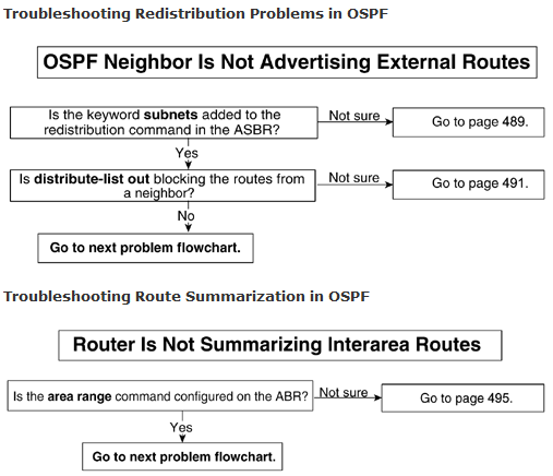
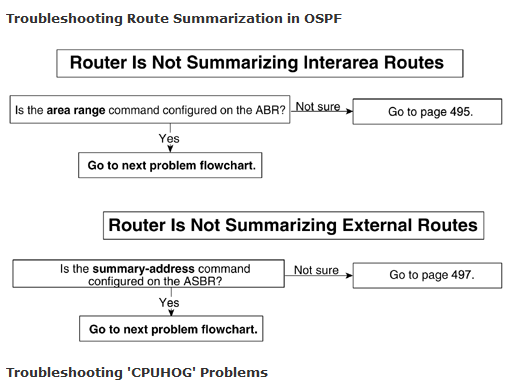
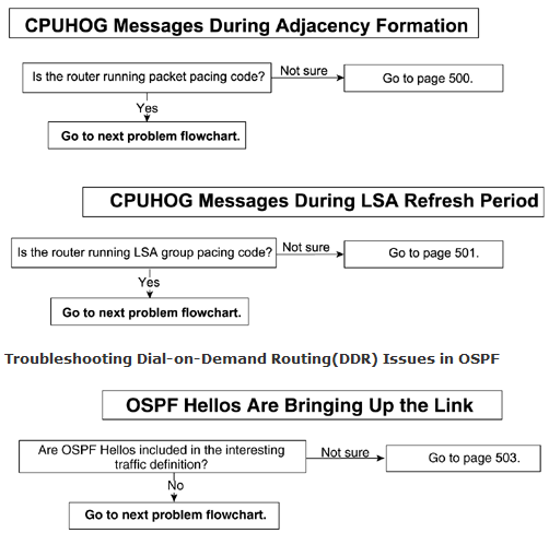
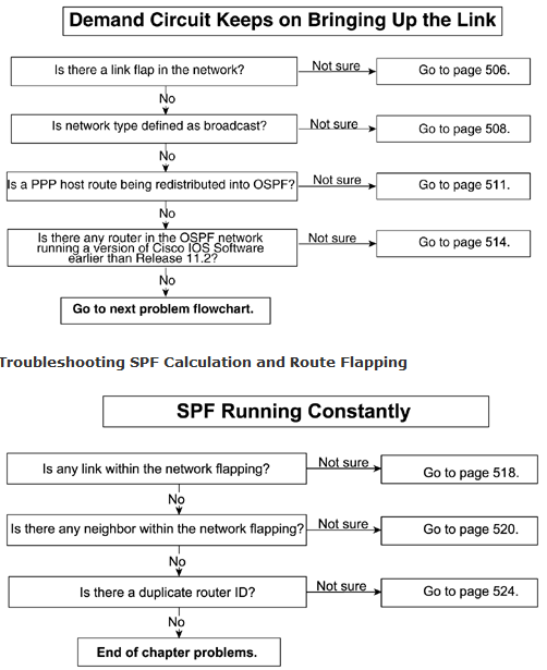
Flowcharts to Solve Common OSPF Problems

Troubleshooting OSPF Neighbor Relationships
This section discusses the problems related to establishing OSPF neighbor relationships. OSPF neighbor relationship problems can be of any type. Sometimes, the neighbor list is empty (that is, an OSPF neighbor might not even see the Hellos from each other). Sometimes, the problem is that the neighbor is stuck in a specific state. Recall from Chapter 8, “Understanding Open Shortest Path First (OSPF),” that the normal state of an OSPF neighbor is FULL. If the state is something other than FULL for a long period of time, this indicates a problem.
This section comes first because this is the most important step in using the OSPF protocol. If no neighbor relationships are established or the neighbors are stuck in a state other than FULL, OSPF will not install any routes in the routing table. Therefore, it is very important in OSPF to make sure that the neighbors are up.
OSPF neighbor relationship problems can be of any of these types:
- The OSPF neighbor list is empty.
- An OSPF neighbor is stuck in ATTEMPT.
- An OSPF neighbor is stuck in INIT.
- An OSPF neighbor is stuck in 2-WAY.
- An OSPF neighbor is stuck in EXSTART/EXCHANGE.
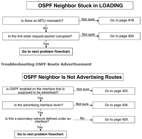
- An OSPF neighbor is stuck in LOADING.
None of the states mentioned in this list is an indication of a problem, but if a neighbor is stuck in one of these states for a long time, this is a problem and must be corrected; otherwise, OSPF will not function properly.
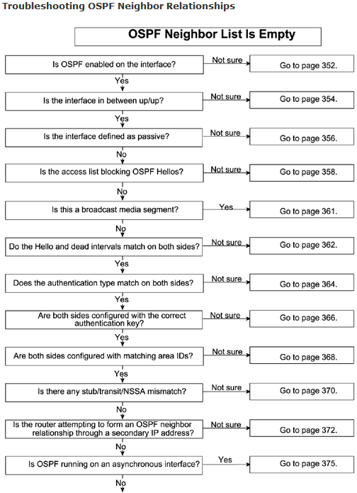
Problem: OSPF Neighbor List Is Empty
This is the most common problem in OSPF neighbor relationships. The most common causes are related to either misconfiguration or lack of configuration. If the neighbor list is empty, it will not even proceed to form OSPF neighbor relationships.
The most common possible causes of this problem are as follows:
- OSPF is not enabled on the interface.
- Layer 1/2 is down.
- The interface is defined as passive under OSPF.
- An access list is blocking OSPF Hellos on both sides.
- A subnet number/mask has been mismatched over a broadcast link.
- The Hello/dead interval has been mismatched.
- The authentication type (plain text versus MD5) has been mismatched.
- An authentication key has been mismatched.
- An area ID has been mismatched.
- Stub/transit/NSSA area options have been mismatched.
- An OSPF adjacency exists with secondary IP addressing.
- An OSPF adjacency exists over an asynchronous interface.
- No network type or neighbor is defined over NBMA (Frame Relay, X.25, SMDS, and so on).
- The frame-relay map/dialer map statement is missing the broadcast keyword on both sides.
Figure 9-1 shows two routers running OSPF between each other. The output of show ip ospf neighbor shows an empty list. In a normal scenario, the output displays the OSPF neighbor status. This figure is used for most of the causes described in this section.

Example 9-1 shows the output of show ip ospf neighbor, which shows the empty neighbor list.
Example 9-1 show ip ospf neighbor Command Output Has an Empty Neighbor List
R2#show ip ospf neighbor
R2#
OSPF Neighbor List Is Empty—Cause: OSPF Not Enabled on the Interface
OSPF can be enabled on a per-interface basis. To enable OSPF on any interface, put a network command under router ospf and include the network address with the wildcard mask. When defining the network statement in OSPF, you should carefully examine the wildcard mask to see the range of addresses it covers. Figure 9-2 shows the flowchart to follow to solve this problem based on this cause.

Debugs and Verification
Example 9-2 shows the configuration of Router R2. The configuration shows that the wrong mask is put under the network statement that includes only loopback 0 into area 0. The network state-ment is determined in OSPF in exactly the same way that you define an access list. The main idea here is to include the range of addresses in an area. In Example 9-2, the network statement of 131.108.0.0 with the wildcard mask of 0.0.0.255 will not cover 131.108.1.2; it covers only the range from 131.108.0.0 to 131.108.0.255, as indicated by the wildcard mask.
Example 9-2 R2 Configuration with the Wrong Mask
R2#
interface Loopback0
ip address 131.108.0.1 255.255.255.0
!
interface Ethernet0
ip address 131.108.1.2 255.255.255.0
!
router ospf 1
network 131.108.0.0 0.0.0.255 area 0
!
Example 9-3 shows the configuration of Router R2. OSPF is not enabled on the Ethernet interface of R2.
Example 9-3 OSPF Not Enabled on R2’s Ethernet 0 Interface
R2#show ip ospf interface Ethernet 0
Ethernet0 is up, line protocol is up
OSPF not enabled on this interface
Solution
Sometimes, the configuration shows the correct mask and the OSPF neighbor list still shows empty. This is a very rare case. During network configuration changes under OSPF, a cut and paste of the OSPF configuration might create this problem. Therefore, you always should look at the output of show ip ospf interface for that specific interface and see whether OSPF is enabled on that interface. This type of problem can be corrected by re-entering the network statement.
If OSPF is not enabled on the interface, the interface is incapable of sending or receiving OSPF Hellos. To correct this problem, change the network mask so that it includes the Ethernet address.
Example 9-4 shows the new configuration that fixes this problem. In this example, the wildcard mask is 0.0.255.255, which means that it covers the range from 131.108.0.0 to 131.108.255.255.
Example 9-4 Fixing the Configuration on R2 to Include the Proper Network Mask
R2#
router ospf 1
network 131.108.0.0 0.0.255.255 area 0
Example 9-5 shows the output of show ip ospf neighbor after applying the correct network mask.
Example 9-5 show ip ospf neighbor Command Output Verifies That OSPF Is Up After the Correct Network Mask Has Been Configured
R2#show ip ospf neighbor
Neighbor ID Pri State Dead Time Address Interface
131.108.2.1 1 FULL/DR 00:00:38 131.108.1.1 Ethernet0
Beginning with Cisco IOS Software Release 12.0, the output of show ip ospf interface doesn’t display anything if OSPF is not enabled on the interface.
OSPF Neighbor List Is Empty—Cause: Layer 1/2 Is Down
OSPF runs at Layer 3 on top of Layer 2. OSPF cannot send or receive any Hellos if Layer 2 is down. One of the causes for OSPF not forming neighbors is that Layers 1 or 2 might be down. If Layer 1 or Layer 2 is down, it’s not a problem directly related to OSPF.
Figure 9-3 shows the flowchart to solve this problem.

Debugs and Verification
Example 9-6 shows the output of show ip ospf interface for Ethernet 0, which shows that the line protocol is down.
Example 9-6 show ip ospf interface Command Output Indicates That the Line Protocol Is Down
R2#show ip ospf interface Ethernet 0
Ethernet0 is up, line protocol is down
Internet Address 131.108.1.2/24, Area 0
Process ID 1, Router ID 131.108.1.2, Network Type BROADCAST, Cost: 10
Transmit Delay is 1 sec, State DOWN, Priority 1
No designated router on this network
No backup designated router on this network
Timer intervals configured, Hello 10, Dead 40, Wait 40, Retransmit 5
Solution
Layers 1 or 2 could be down for several reasons. The list that follows covers some of the most common things to check to determine whether the interface or line protocol is down:
- Unplugged cable
- Loose cable
- Bad cable
- Bad transceiver
- Bad port
- Bad interface card
- Layer 2 problem at telco in case of a WAN link
- Missing clock statement in case of back-to-back serial connections
To correct this problem, fix the Layer 2 problem by checking the previously mentioned conditions. Example 9-7 shows the output of show ip ospf interface for Ethernet 0 after fixing the Layer 2 problem.
Example 9-7 Verifying That Layer 2 Is Up
R2#show ip ospf interface Ethernet 0
Ethernet0 is up, line protocol is up
Internet Address 131.108.1.2/24, Area 4
Process ID 1, Router ID 131.108.1.2, Network Type BROADCAST, Cost: 10
Transmit Delay is 1 sec, State BDR, Priority 1
Designated Router (ID) 131.108.2.1, Interface address 131.108.1.1
Backup Designated router (ID) 131.108.1.2, Interface address 131.108.1.2
Timer intervals configured, Hello 10, Dead 40, Wait 40, Retransmit 5
Hello due in 00:00:07
Neighbor Count is 1, Adjacent neighbor count is 1
Adjacent with neighbor 131.108.1.1 (Designated Router)
Suppress hello for 0 neighbor(s)
Example 9-8 shows the output of show ip ospf neighbor, which shows that OSPF adjacency is FULL.
Example 9-8 Verifying OSPF Adjacency State
R2#show ip ospf neighbor
Neighbor ID Pri State Dead Time Address Interface
131.108.2.1 1 FULL/DR 00:00:39 131.108.1.1 Ethernet0
OSPF Neighbor List Is Empty—Cause: Interface Is Defined as Passive Under OSPF
When an interface is defined as passive under router OSPF, it suppresses OSPF Hellos. This means that OSPF does not send or receive any Hellos on such interfaces. Therefore, no adjacency is formed.
Figure 9-4 shows a flowchart to solve this problem.

Debugs and Verification
Example 9-9 shows the output of show ip ospf interface for Ethernet 0 of Router R2. This command shows that this interface is defined as passive.
Example 9-9 Determining Whether an Interface Is Defined as Passive
R2#show ip ospf interface Ethernet 0
Ethernet0 is up, line protocol is up
Internet Address 131.108.1.2/24, Area 0
Process ID 1, Router ID 131.108.1.2, Network Type BROADCAST, Cost: 10
Transmit Delay is 1 sec, State DR, Priority 1
Designated Router (ID) 131.108.1.2, Interface address 131.108.1.2
No backup designated router on this network
Timer intervals configured, Hello 10, Dead 40, Wait 40, Retransmit 5
No Hellos (Passive interface)
Neighbor Count is 0, Adjacent neighbor count is 0
Suppress hello for 0 neighbor(s)
Example 9-10 shows the configuration of Router R2. This configuration shows that the Ethernet 0 of R2 is defined as passive.
Example 9-10 The Ethernet 0 Interface of R2 Is Defined as Passive
R2#
interface Loopback0
ip address 131.108.0.1 255.255.255.0
!
interface Ethernet0
ip address 131.108.1.2 255.255.255.0
!
router ospf 1
passive-interface Ethernet0
network 131.108.0.0 0.0.255.255 area 0
Solution
To correct this problem, remove the passive-interface command from the OSPF configuration. Sometimes, the command is entered intentionally so that the router cannot take part in any OSPF process on that segment. This is the case when you don’t want to form any neighbor relationship on an interface but you do want to advertise that interface.
Sometimes, the intention is not to send any routes but to receive all routes on that interface, just as with RIP or IGRP. Remember, defining a passive interface under RIP or IGRP has a different meaning than defining a passive interface under OSPF or EIGRP. When RIP or IGRP is defined as passive, RIP or IGRP will not send any routing updates on that interface but will receive all the routing updates on that interface. In OSPF, a passive interface means “do not send or receive OSPF Hellos on this interface.” So, making an interface passive under OSPF with the intention of preventing the router from sending any routes on that interface but receiving all the routes is wrong.
Example 9-11 shows the new configuration of Router R2. The passive-interface command is removed from the configuration.
Example 9-11 Removing the Passive Interface Definition from a Router Interface
router ospf 1
no passive-interface Ethernet0
network 131.108.0.0 0.0.255.255 area 0
Example 9-12 shows that OSPF is forming adjacency after removing the passive-interface command.
Example 9-12 Verifying the New Interface Definition Corrects the Problem
R2#show ip ospf neighbor
Neighbor ID Pri State Dead Time Address Interface
131.108.2.1 1 FULL/DR 00:00:37 131.108.1.1 Ethernet0
OSPF Neighbor List Is Empty—Cause: Access List Blocking OSPF Hellos on Both Sides
OSPF sends its Hello on a multicast address of 224.0.0.5. All OSPF-enabled interfaces listen to this address. It is very common to implement an access list for security measures at the interface level. Be sure to permit OSPF multicast Hellos’ addresses in the access list in this situation; otherwise, the access list might block the OSPF multicast address unknowingly and prevent OSPF from forming neighbors on that interface.
This situation happens only when the access list is blocking Hellos on both routers. If only one side is blocking OSPF Hellos, the output of show ip ospf neighbor will indicate that the neighbor is stuck in the INIT state. This case is discussed later in this chapter.
Figure 9-5 shows the flowchart to follow to solve this problem.

Debugs and Verification
Example 9-13 shows the configuration of both Routers R1 and R2, which shows that the access list is permitting only incoming TCP and UDP traffic. The inbound access list checks only traffic coming in on that interface. Because there is an implicit deny at the end of each access list, this access list will block the OSPF multicast address of 224.0.0.5. Access list 101 in Example 9-13 is defined for debugging purposes only. This access list looks at the IP packets sourcing from 131.108.1.0–255 addresses destined for OSPF multicast address of 224.0.0.5.
Example 9-13 Access List Configuration for R1 and R2
R1#
interface Ethernet0
ip address 131.108.1.1 255.255.255.0
ip access-group 100 in
!
access-list 100 permit tcp any any
access-list 100 permit udp any any
access-list 101 permit ip 131.108.1.0 0.0.0.255 host 224.0.0.5
_____________________________________________________________________________________
R2#
interface Ethernet0
ip address 131.108.1.2 255.255.255.0
ip access-group 100 in
!
access-list 100 permit tcp any any
access-list 100 permit udp any any
access-list 101 permit ip 131.108.1.0 0.0.0.255 host 224.0.0.5
Example 9-14 shows the output of debug ip packet 101 detail. This debug tracks down the OSPF Hello packet only on the Ethernet segment. The debug shows that the OSPF Hello packet from Router R1 is denied on R2.
Example 9-14 debug Shows That the OSPF Multicast Packets Are Being Denied
R2#debug ip packet 101 detail
IP packet debugging is on (detailed) for access list 101
IP: s=131.108.1.2 (Ethernet0), d=224.0.0.5, len 68, access denied, proto=89
Solution
To correct this problem, you must reconfigure the access list to permit OSPF multicast Hellos. Example 9-15 shows the configuration that fixes this problem. In this configuration, OSPF multicast Hellos are permitted.
Example 9-15 Configuring the Access List to Permit the OSPF Multicast Address
interface Ethernet0
ip address 131.108.1.2 255.255.255.0
ip access-group 100 in
!
access-list 100 permit tcp any any
access-list 100 permit udp any any
access-list 100 permit ip any host 224.0.0.5
Similarly, change the access list on the other side, making sure that the OSPF Hellos are permitted in the access list. Example 9-16 shows the OSPF neighbor in FULL state after fixing the configuration.
Example 9-16 Verifying That the Reconfigured Access List Has Resolved the Problem
R2#show ip ospf neighbor
Neighbor ID Pri State Dead Time Address Interface
131.108.2.1 1 FULL/DR 00:00:37 131.108.1.1 Ethernet0
OSPF Neighbor List Is Empty—Cause: Mismatched Subnet Number/Mask over a Broadcast Link
OSPF performs the subnet number and mask check on all media except point-to-point and virtual links as specified, by Section 10.5 of OSPF RFC 2328. For purposes of this scenario, the medium is Ethernet and the network type on Ethernet is broadcast. The network mask gets advertised in the Hello packet. In the case of unnumbered point-to-point links and virtual links, the network mask field contains 0.0.0.0. If the subnet mask is different across the Ethernet link, OSPF will not form a neighbor relationship on that link.
Figure 9-6 shows the flowchart to follow to solve this problem.

Debugs and Verification
Example 9-17 shows the output of debug ip ospf adj. This debug shows that there is a mis-matched Hello parameter. The neighbor subnet mask is 255.255.255.252 and Router R2’s subnet mask is 255.255.255.0.
Example 9-17 debug ipo ospf adj Command Output Indicates a Mismatched Hello Parameter
R2##debug ip ospf adj
OSPF adjacency events debugging is on
R2#
OSPF: Rcv hello from 131.108.2.1 area 4 from Ethernet0 131.108.1.1
OSPF: Mismatched hello parameters from 131.108.2.1
Dead R 40 C 40, Hello R 10 C 10 Mask R 255.255.255.248 C 255.255.255.0
The letter R means “neighbor configuration,” and C means “this router configuration.” In the case of different subnet numbers the debug message will be
OSPF: Rcv pkt from 131.108.1.1, Ethernet0, area 0.0.0.1 : src not on the same network
Example 9-18 shows the configuration of both Routers R1 and R2, which shows that both routers’ Ethernets have different subnet masks.
Example 9-18 Configurations for R1 and R2 Have Different Subnet Masks
R2#
interface Ethernet0
ip address 131.108.1.2 255.255.255.0
_____________________________________________________________________________________
R1#
interface Ethernet0
ip address 131.108.1.1 255.255.248.0
Solution
To fix this problem, change the neighbor’s (R1’s) subnet mask to match Router R2’s, or change the subnet mask of R2 to match the neighbor’s subnet mask. Assume here that you changed the subnet mask of R1 to 255.255.255.0 to match with R2.
Example 9-19 shows that after fixing the subnet network/mask, adjacency is FULL.
Example 9-19 Verify That Subnet Masks for R1 and R2 Now Match
R2#show ip ospf neighbor
Neighbor ID Pri State Dead Time Address Interface
131.108.2.1 1 FULL/DR 00:00:31 131.108.1.1 Ethernet0
OSPF Neighbor List Is Empty—Cause: Mismatched Hello/Dead Intervals
OSPF neighbors exchange Hello packets periodically to form and maintain neighbor relation-ships. OSPF advertises the router’s Hello and dead intervals in the Hello packets. These intervals must match with the neighbor’s; otherwise, an adjacency will not form.
Figure 9-7 shows the flowchart to follow to solve this problem.

Debugs and Verification
Example 9-20 shows the output of debug ip ospf adj, which indicates that the neighbor’s Hello interval does not match with Router R2’s.
Example 9-20 Verifying Mismatched Hello Intervals Between OSPF Neighbors
R2#debug ip ospf adj
OSPF adjacency events debugging is on
R2#
OSPF: Rcv hello from 131.108.2.1 area 4 from Ethernet0 131.108.1.1
OSPF: Mismatched hello parameters from 131.108.2.1
Dead R 40 C 40, Hello R 15 C 10 Mask R 255.255.255.0 C 255.255.255.0
Example 9-21 shows the configuration of both Routers R1 and R2. In R1, the Hello interval is configured as 15 seconds. In R2, the Hello interval defaults to 10 seconds.
Example 9-21 Hello Interval Configurations for R1 and R2
R2#
interface Ethernet0
_____________________________________________________________________________________
R1#
interface Ethernet0
ip address 131.108.1.1 255.255.248.0
ip ospf hello-interval 15
Solution
This example shows a problem when the Hello interval configured for OSPF neighbors doesn’t match. The same problem happens when the dead interval doesn’t match between OSPF neighbors. In both cases, the solution is to change the Hello/dead interval to be consistent between OSPF neighbors. Unless there are any specific reasons to deviate from the default settings, the Hello and dead intervals should be kept to their default values.
In Example 9-22, the configuration on R1 is changed so that it uses the default value for the Hello interval on Ethernet, which is 10 seconds. Removing the Hello interval changes the Hello interval value back to its default.
Example 9-22 Changing Hello Interval to Its Default Value
R1
interface Ethernet0
ip address 131.108.1.1 255.255.248.0
no ip ospf hello-interval 15
Example 9-23 shows that after fixing the Hello and dead intervals, OSPF forms an adjacency.
Example 9-23 Verifying That OSPF Is Forming Neighbors After Matching Hello/Dead Intervals
R2#show ip ospf neighbor
Neighbor ID Pri State Dead Time Address Interface
131.108.2.1 1 FULL/DR 00:00:32 131.108.1.1 Ethernet0
OSPF Neighbor List Is Empty—Cause: Mismatched Authentication Type
OSPF uses two types of authentication, plain-text (Type 1) and MD5 (Type 2). Type 0 is called null authentication. If the plain-text authentication type is enabled on one side, the other side must also have plain-text authentication. OSPF will not form an adjacency unless both sides agree on the same authentication type.
In one situation, one side is configured for plain-text or MD5 authentication but the other side is not configured for any authentication. This situation creates a case of an OSPF neighbor being stuck in INIT, which is discussed later in this chapter.
Figure 9-8 shows the flowchart to follow to solve this problem.

Debugs and Verification
Example 9-24 shows the output of debug ip ospf adj, indicating that R2’s neighbor is configured for MD5 authentication and that R2 is configured for plain-text authentication.
Example 9-24 debug Shows Mismatched Authentication Type
R2#debug ip ospf adj
OSPF adjacency events debugging is on
R2#
OSPF: Rcv pkt from 131.108.1.1, Ethernet0 : Mismatch Authentication type. Input packet
specified type 2, we use type 1
Example 9-25 shows the configuration of both Routers R1 and R2, indicating that R2 is using plain-text authentication and R1 is using MD5 authentication.
Example 9-25 Authentication Type Configuration for R1 and R2
R2#
router ospf 1
area 0 authentication
network 131.108.0.0 0.0.255.255 area 0
_____________________________________________________________________________________
R1#
router ospf 1
area 0 authentication message-digest
network 131.108.0.0 0.0.255.255 area 0
Solution
To fix this problem, make sure that both sides are using the same authentication type. Example 9-26 shows that after using a consistent authentication type, OSPF forms the adjacency, as indicated by the FULL state.
Example 9-26 Verifying That the Authentication Type Between OSPF Neighbors Is Now Consistent
R2#show ip ospf neighbor
Neighbor ID Pri State Dead Time Address Interface
131.108.2.1 1 FULL/DR 00:00:32 131.108.1.1 Ethernet0
OSPF Neighbor List Is Empty—Cause: Mismatched Authentication Key
When authentication is enabled, the authentication key also must be configured on the interface. Authentication previously was supported on a per-area basis, but beginning with the specifications in RFC 2328, authentication is supported on a per-interface basis. This feature has been implemented in Cisco IOS Software Release 12.0.8 and later.
If authentication is enabled on one side but not the other, OSPF complains about the mismatch in authentication type. Sometimes, the authentication key is configured correctly on both sides but debug ip ospf adj still complains about a mismatched authentication type. In this situation, authentication-key must be typed again because there is a chance that a space was added during the authentication key configuration by mistake. Because the space character is not visible in the configuration, this part is difficult to determine.
Another possible thing that can go wrong is for one side, R1, to have a plain-text key configured and the other side, R2, to have an MD5 key configured, even though the authentication type is plain text. In this situation, the MD5 key is completely ignored by R2 because MD5 has not been enabled on the router. This is equivalent to not having any plain-text key configured under the interface. For more information on authentication, refer to Chapter 8.
Figure 9-9 shows the flowchart to follow to solve this problem.

Debugs and Verification
Example 9-27 shows the output of debug ip ospf adj, which shows that there is an authentication key mismatch.
Example 9-27 Detecting an Authentication Key Mismatch
R2#debug ip ospf adj
OSPF adjacency events debugging is on
R2#
OSPF: Rcv pkt from 131.108.1.1, Ethernet0 : Mismatch Authentication Key – Clear Text
Example 9-28 shows the configuration of R1 and R2. Note that R2 is not configured for any authentication key, whereas R1 is configured with an authentication key that is causing this problem.
Example 9-28 Configuration of R1 and R2
R2#
interface Ethernet0
ip address 131.108.1.2 255.255.255.0
_____________________________________________________________________________________
R1#
interface Ethernet0
ip address 131.108.1.1 255.255.248.0
ip ospf authentication-key Cisco
Solution
To solve this problem, make sure that both sides have the same kind of authentication key. If the problem still exists, retype the authentication key; there is a possibility of an added space character before or after the authentication key.
Example 9-29 shows the output of show ip ospf neighbor after fixing this problem.
Example 9-29 Verifying That OSPF Neighbors Are Up After Using Identical Authentication Keys
R2#show ip ospf neighbor
Neighbor ID Pri State Dead Time Address Interface
131.108.2.1 1 FULL/DR 00:00:32 131.108.1.1 Ethernet0
OSPF Neighbor List Is Empty—Cause: Mismatched Area ID
OSPF sends area information in the Hello packets. If both sides do not agree that they are members of a common area, no OSPF adjacency will be formed. The area information is a part of the OSPF protocol header.
Figure 9-10 shows the flowchart to follow to solve this problem.

Debugs and Verification
Example 9-30 shows the configuration of R2 and R1. Refer back to Figure 9-1; if R1’s Ethernet interface is included in area 0 and R2’s Ethernet is included in area 1, it will cause area ID mismatch.
Example 9-30 Area Configurations for Interfaces on R1 and R2
R2#
interface Ethernet0
ip address 131.108.1.2 255.255.255.0
!
router ospf 1
network 131.108.0.0 0.0.255.255 area 1
_____________________________________________________________________________________
R1#
interface Ethernet0
ip address 131.108.1.1 255.255.255.0
!
router ospf 1
network 131.108.0.0 0.0.255.255 area 0
Example 9-31 shows the output of debug ip ospf adj on R1, indicating that R1 is receiving an OSPF packet from R2 and that the OSPF header has area 0.0.0.1 in it. This proves that the other side is configured for area 0.0.0.1 instead of area 0. There is no need to check the other side’s configuration in this case.
Example 9-31 Determining the OSPF Neighbor Area Configuration
R1#debug ip ospf adj
OSPF adjacency events debugging is on
R1#
OSPF: Rcv pkt from 131.108.1.2, Ethernet0, area 0.0.0.0
mismatch area 0.0.0.1 in the header
Example 9-32 shows the console log of R2. This log shows that R1 is receiving an OSPF packet that has area 0.0.0.0 in the OSPF header. Because this router is not configured for area 0, it receives this message at the console log level. If the neighbor Router R1 is configured with some other area, the only way to find out about area mismatch is to turn on debug ip ospf adj, as in case of R1.
Example 9-32 Console Logs of R2 Showing Mismatch Area
R2#show log
%OSPF-4-ERRRCV: Received invalid packet: mismatch area ID, from backbone area must be
virtual-link but not found from 131.108.1.1, Ethernet0
Solution
To solve this problem, configure the same area across the link. Example 9-33 shows that the R1 configuration has been changed so that the area ID of R1 now matches R2’s.
Example 9-33 Corrected Configuration on R1
R1#
interface Ethernet0
ip address 131.108.1.1 255.255.255.
!
router ospf 1
no network 131.108.0.0 0.0.255.255 area 0
network 131.108.0.0 0.0.255.255 area 1
Example 9-34 shows that after fixing this problem, OSPF formed an adjacency.
Example 9-34 Verifying OSPF Neighbors After Fixing the Mismatched Area ID
R2#show ip ospf neighbor
Neighbor ID Pri State Dead Time Address Interface
131.108.2.1 1 FULL/DR 00:00:32 131.108.1.1 Ethernet0
OSPF Neighbor List Is Empty—Cause: Mismatched Stub/Transit/NSSA Area Options
When OSPF exchanges Hello packets with a neighbor, one of the things that it exchanges in the Hello packet is an optional capability represented by 8 bits. One of the option fields is for the E bit, which is the OSPF stub area flag. When the E bit is set to 0, the area with which the router is associated is a stub area, and no external LSAs are allowed in this area.
If one side has the E bit set to 0 and the other side doesn’t, OSPF adjacency is not formed. This is called an optional capability mismatch. One side says that it can allow external routes, and the other side says that it cannot allow external routes, so OSPF neighbor relationships are not formed.
Figure 9-11 shows the flowchart to follow to solve this problem.

Debugs and Verification
Example 9-35 shows the configuration of Routers R1 and R2. R2’s configuration shows that area 1 is configured as a stub, but R1’s area 1 is configured as a standard area.
Example 9-35 Area Configuration for R1 and R2
R2#
interface Ethernet0
ip address 131.108.1.2 255.255.255.0
!
router ospf 1
area 1 stub
network 131.108.0.0 0.0.255.255 area 1
_____________________________________________________________________________________
R1#
interface Ethernet0
ip address 131.108.1.1 255.255.255.0
!
router ospf 1
network 131.108.0.0 0.0.255.255 area 1
Example 9-36 shows the output of debug ip ospf adj on R1. This debug shows the problem as a stub/transit mismatch.
Example 9-36 debug ip ospf adj Command Output Determines a Stub/Transit Area Option Bit Mismatch
R1#debug ip ospf adj
OSPF adjacency events debugging is on
R1#
OSPF: Rcv hello from 131.108.0.1 area 1 from Ethernet0 131.108.1.2
OSPF: Hello from 131.108.1.2 with mismatched Stub/Transit area option bit
Solution
To solve this problem, make sure that both sides agree on the same type of area. This example talks about only the stub area, but a similar problem can happen if one side is configured for stub and the other side is configured as an OSPF NSSA. Another situation is that one side is configured for NSSA and the other side is configured for a normal area. In any case, whenever there is a mismatched area type, OSPF adjacency will not be formed.
Example 9-37 shows the debug ip ospf adj output in the case of an NSSA area mismatch.
Example 9-37 debug ip ospf adj Command Output Determines an NSSA Option Bit Mismatch
R1#debug ip ospf adj
OSPF adjacency events debugging is on
R1#
OSPF: Rcv hello from 131.108.0.1 area 1 from Ethernet0 131.108.1.2
OSPF: Hello from 131.108.1.2 with mismatched NSSA option bit
Example 9-38 shows a configuration change on R1 that fixes the problem. Now R1 is also a part of the stub area.
Example 9-38 Configuration Change on R1 That Fixes the Problem
R1#
interface Ethernet0
ip address 131.108.1.1 255.255.255.0
!
router ospf 1
area 1 stub
network 131.108.0.0 0.0.255.255 area 1
Example 9-39 shows the output of show ip ospf neighbor after fixing this problem.
Example 9-39 Verifying That OSPF Neighbors Are Up After Fixing the Mismatch Stub/NSSA Problem
R2#show ip ospf neighbor
Neighbor ID Pri State Dead Time Address Interface
131.108.2.1 1 FULL/DR 00:00:32 131.108.1.1 Ethernet0
OSPF Neighbor List Is Empty—Cause: OSPF Adjacency Over Secondary IP Address
This is a very common problem in which a customer might have one Class C address on a LAN segment. When the customer runs out of address space, he gets another Class C address and assigns the new address as a secondary address under the same interface. Everything works fine until two routers must exchange OSPF Hellos/updates and one router’s primary IP ad-dress is assigned as the secondary IP address on the other side, as depicted in the network in Figure 9-12. The two routers are connected through a Layer 2 switch.

Figure 9-13 shows the flowchart to follow to solve this problem.

Debugs and Verification
Example 9-40 shows the configuration of both R1 and R2. The configuration illustrates that R2 has a primary and a secondary address configured on its Ethernet interface, and that the subnet number used for the primary address on R1 is for the secondary address on R2.
Example 9-40 R2’s FastEthernet0/0 Interface Secondary Address Configuration Matches R1’s Ethernet0 Interface Primary Address Configuration
R2#
interface FastEthernet0/0
ip address 131.108.1.2 255.255.255.0 secondary
ip address 131.108.4.2 255.255.255.0
_____________________________________________________________________________________
R1#
interface Ethernet0
ip address 131.108.1.1 255.255.255.0
Example 9-41 shows the output of debug ip ospf adj. This output is exactly the same as the debug output in case of a mismatched subnet number. This is because, when R1 receives a Hello packet from R2, the source address will be 131.108.4.2, which is a different subnet than its connected interface. As a result, R1 will complain.
Example 9-41 debug ip ospf adj Command Output Indicates an IP Address Conflict
R2#debug ip ospf adj
OSPF adjacency events debugging is on
R2#
OSPF: Rcv pkt from 131.108.1.1, FastEthernet0/0, area 0.0.0.1 : src not on the same
network
Solution
The solution to this kind of problem is to create subinterfaces on R1. This is possible only if the interface that has the secondary address is Fast Ethernet or Gigabit Ethernet and it is con-nected through a Layer 2 switch. This can be achieved through an Inter-Switch Link (ISL), in the case of a Cisco switch, or dot1Q encapsulation, in the case of a different vendor’s switch. ISL or dot1Q encapsulation is used to route between two separate VLANs. The switch port that connects to the Fast Ethernet interface of R2 is configured as a trunk port, so all the traffic between VLAN 1 and VLAN 2 will go through the router and the router will route between these two VLANs.
Example 9-42 shows the configuration of R1 and a Cisco switch to use an ISL trunk so that it can create subinterfaces on R2.
Example 9-42 Creating Subinterfaces on R2
R2#
interface FastEthernet0/0
no ip address
full-duplex
!
interface FastEthernet0/0.1
encapsulation isl 2
ip address 131.108.1.2 255.255.255.0
interface FastEthernet0/0.2
encapsulation isl
ip address 131.108.4.2 255.255.255.0
cat-5k-1> (enable) set trunk 11/10 on
Port(s) 11/10 trunk mode set to on
Example 9-42 shows the example of how to create subinterfaces and how to enable VLAN trunking on the Cisco Catalyst switch. R1’s Fast Ethernet interface is included in VLAN 2, and the subinterface of R2, FE 0/0.1, also is added in VLAN 2. Also, port 11/10 of the switch that connects to R2 is enabled for trunking so that it will carry both VLAN 1 and VLAN 2 traffic. Similar configurations can be implemented in the case of 802.1Q encapsulation. Figure 9-14 shows the logical picture after making this change. FE 0/0.1 is a subinterface using ISL encapsulation.

After making this change, R2 will form a neighbor relationship with R1 on FE 0/0.1. The other subinterface, FE 0/0.2, which is in VLAN 1, will form a neighbor relationship with other routers in VLAN 1.
FE 0/0.1 and FE 0/0.2 are logical subinterfaces. This means that both of these subinterfaces are subsets of one physical interface (FE 0/0) that connects to port 11/10 of the switch. Example 9-43 shows the output of show ip ospf neighbor after making this change.
Example 9-43 OSPF Forming Neighbors After Creating Subinterface
R2#show ip ospf neighbor
Neighbor ID Pri State Dead Time Address Interface
131.108.2.1 1 FULL/DR 00:00:32 131.108.1.1 FastEthernet0/0.1
OSPF Neighbor List Is Empty—Cause: OSPF Adjacency over Asynchronous Interface
You must enable asynchronous default or dynamic routing when OSPF is enabled between two routers over asynchronous interface. When async default routing is enabled, the router always sends routing packets over an asynchronous interface. In case of interactive asynchronous connections for which users have to type ppp to establish the PPP session, the async dynamic routing command can be used, but then users must type ppp /routing to enable routing over the asynchronous interface. An inability to do this causes OSPF not to form any adjacency over the asynchronous link.
Figure 9-15 shows the network diagram with the two routers running OSPF between asynchronous interfaces.

Figure 9-16 shows the flowchart to follow to solve this problem.

Debugs and Verification
Example 9-44 shows the configuration of R1 and R2. This configuration shows that asynchronous default routing is missing from the interface configuration.
Example 9-44 Verifying That Asynchronous Default Routing Is Missing on the Asynchronous Interfaces of R1 and R2
R1#
interface Async1
description ASYNC LINE TO R2
ip address 131.108.1.1 255.255.255.0
encapsulation ppp
async mode dedicated
dialer in-ban
dialer map ip 131.108.1.2 name Router2 broadcast
dialer-group 1
ppp authentication chap
_____________________________________________________________________________________
R2#
interface Async1
description ASYNC LINE TO R1
ip address 131.108.1.2 255.255.255.0
encapsulation ppp
async mode dedicated
dialer in-band
dialer map ip 131.108.1.1 name Router2 broadcast
dialer-group 1
ppp authentication chap
Solution
In this example, use either async default routing or asyn dynamic routing to solve this problem.
Example 9-45 shows the configurations of R1 and R2 after using async default routing.
Example 9-45 Configuring R1 and R2 to Use async default routing
R1#
interface Async1
description ASYNC LINE TO R2
ip address 131.108.1.1 255.255.255.0
encapsulation pp
async default routing
async mode dedicated
dialer in-band
dialer map ip 131.108.1.2 name Router2 broadcast
dialer-group 1
ppp authentication chap
___________________________________________________________________________________
R2#
interface Async1
description ASYNC LINE TO R1
ip address 131.108.1.2 255.255.255.0
encapsulation ppp
async default routing
async mode dedicated
dialer in-band
dialer map ip 131.108.1.1 name Router2 broadcast
dialer-group 1
ppp authentication chap
Example 9-46 shows that OSPF forms neighbor relationships after fixing this problem.
Example 9-46 Verifying That R1 and R2 Are Forming Neighbors After Using async default routing
R2#show ip ospf neighbor
Neighbor ID Pri State Dead Time Address Interface
131.108.2.1 1 FULL/- 00:00:32 131.108.1.1 Async1
OSPF Neighbor List Is Empty—Cause: No Network Type or Neighbor Defined over NBMA
This is a classic problem of NBMA networks. OSPF or any other routing protocol will not be capable of sending or receiving any Hello packet unless you configure a neighbor statement or change the network type to broadcast or point-to-multipoint. When the neighbor statement is configured, it triggers OSPF Hellos and neighbor relationships are formed. Changing the network type also changes the interface behavior; in the case of the broadcast network type, OSPF starts sending and receiving the OSPF Hellos. Chapter 8 provides a detailed explanation of OSPF network types.
Figure 9-17 shows the network diagram with two routers running OSPF in Frame Relay cloud. Frame Relay is just one example; this problem can be produced in any nonbroadcast network, such as X.25, SMDS, and so on.

Figure 9-18 shows the flowchart to follow to solve this problem.

Debugs and Verification
Example 9-47 shows the output of show interface serial0 on R2. The network type is showing as nonbroadcast. Any nonbroadcast interface—for example, X.25, SMDS, Frame Relay, and so on—always shows the network type as nonbroadcast.
Example 9-47 Determining the Network Type on R2’s Serial0 Interface
R2#show ip ospf interface serial0
Serial0 is up, line protocol is up
Internet Address 131.108.1.2/24, Area 1
Process ID 1, Router ID 131.108.1.2, Network Type NON_BROADCAST, Cost: 64
Transmit Delay is 1 sec, State DR, Priority 1
Designated Router (ID) 131.108.1.2, Interface address 131.108.1.2
No backup designated router on this network
Timer intervals configured, Hello 30, Dead 120, Wait 120, Retransmit 5
Hello due in 00:00:00
Neighbor Count is 0, Adjacent neighbor count is 0
Suppress hello for 0 neighbor(s)
Solution
To solve this problem, configure the neighbor statement under router ospf, as done in Example 9-48. By configuring the neighbor statement, OSPF starts sending the Hello packet as a unicast instead of a multicast. This is also a useful technique when the multicast cap-abilities of any medium are broken. Be sure to define the right neighbor address; otherwise, the OSPF Hello packet will not make it to the neighbor.
Example 9-48 OSPF Configuration with neighbor Statement
R2#
router ospf
network 131.108.0.0 0.0.255.255 area 1
neighbor 131.108.1.1 priority 1
Other methods to solve this problem include changing the network type to either broadcast or point-to-multipoint. In this case, OSPF starts sending the multicast Hellos across the link. Example 9-49 shows how to change the network type to broadcast and then shows the output of show interface serial0 after using the network type broadcast.
Example 9-49 Verifying That the Broadcast Network Type Configuration Is Allowing OSPF to Form an Adjacency
R2#
interface Serial 0
ip ospf network broadcast
R2#show ip ospf interface serial0
Serial0 is up, line protocol is up
Internet Address 131.108.1.2, Area 1
Process ID 1, Router ID 131.108.1.2, Network Type BROADCAST, Cost: 64
Transmit Delay is 1 sec, State BDR, Priority 1
Designated Router (ID) 131.108.2.1, Interface address 131.108.1.1
Backup Designated router (ID) 131.108.1.2, Interface address 131.108.1.2
Timer intervals configured, Hello 10, Dead 40, Wait 40, Retransmit 5
Hello due in 00:00:05
Neighbor Count is 1, Adjacent neighbor count is 1
Adjacent with neighbor 131.108.2.1 (Designated Router)
Suppress hello for 0 neighbor(s)
Similarly, changing the network type to point-to-multipoint will make it work. Example 9-50 shows how to change the network type to point-to-point and then shows the output of show ip ospf neighbor, which shows that the neighbors are FULL across the serial link after making the change.
Example 9-50 Verifying That the Point-to-Multipoint Network Type Configuration Is Allowing OSPF to Form Adjacency
R2#
interface Serial 0
ip ospf network point-to-multipoint
R2#show ip ospf neighbor
Neighbor ID Pri State Dead Time Address Interface
131.108.2.1 1 FULL/- 00:01:42 131.108.1.1 Serial0
OSPF Neighbor List Is Empty—Cause: Frame Relay/Dialer Interface Missing the broadcast Keyword on Both Sides
OSPF uses multicast Hellos to form adjacencies. Other routing protocols—for example, RIP and EIGRP—also use broadcasts or multicasts to form neighbor relationships. In the case of Frame Relay or dialer interfaces, you must enable the broadcast keyword in frame-relay or dialer-map statements on both ends to propagate OSPF Hellos. These maps statements are valid only if the interfaces are multipoint in nature. For example, by default, Frame Relay interfaces are multipoint. Also, the BRI interface is multipoint because it is capable of dialing more than one number.
One thing to note here is that both sides should have this broadcast keyword missing from the frame-relay map or dialer-map configurations to produce this problem. If just one side is missing the broadcast keyword, the other side will see this router in INIT and the neighbors will never become adjacent. This case is discussed later in this chapter in the section “Problem: OSPF Neighbor Stuck in INIT.”
Figure 9-19 shows the flowchart to follow to solve this problem.

Debugs and Verification
Example 9-51 shows the output of debug ip packet 100 detail, which indicates that the Hello packets generated from R1 are not getting across because of encapsulation failure. The access list here is used only for the debugging purpose. This access list monitors those IP packets that are sourcing from 131.108.1.1 and 131.108.1.2 and destined for 224.0.0.5.
Example 9-51 Verifying That OSPF Hellos Are Being Dropped Because of Encapsulation Failure
R1#show access-list 100
Extended IP access list 100
permit ip 131.108.1.0 0.0.0.3 host 224.0.0.5 (8 matches)
R1#debug ip packet 100 detail
IP packet debugging is on (detailed) for access list 100
R1#
IP: s=131.108.1.2 (Serial0), d=224.0.0.5, len 64, rcvd 0, proto=89
IP: s=131.108.1.1 (local), d=224.0.0.5 (Serial0), len 68, sending broad/multicast,
proto=
89
IP: s=131.108.1.1 (local), d=224.0.0.5 (Serial0), len 68, encapsulation failed, proto=
89
Example 9-52 shows the configuration of R1 and R2. The configuration shows that the broadcast keyword is missing from the frame-relay map statements.
Example 9-52 Configurations for R1 and R2 Reveal Missing broadcast Keywords
R1#
interface Serial0
ip address 131.108.1.1 255.255.255.0
encapsulation frame-relay
frame-relay map ip 131.108.1.2 16
_____________________________________________________________________________________
R2#
interface Serial0
ip address 131.108.1.2 255.255.255.0
encapsulation frame-relay
frame-relay map ip 131.108.1.1 16
Solution
Example 9-53 shows the modified configurations for R1 and R2 that fixes this problem. Again, the keyword broadcast must be enabled on both sides. If it is enabled on only one side, it will produce a stuck in INIT problem, which is discussed later in this chapter.
Example 9-53 Adding the broadcast Keyword to the frame-relay map Statements for R1 and R2
R1#
interface Serial0
ip address 131.108.1.1 255.255.255.0
encapsulation frame-relay
ip ospf network broadcast
frame-relay map ip 131.108.1.2 16 broadcast
_____________________________________________________________________________________
R2#
interface Serial0
ip address 131.108.1.2 255.255.255.0
encapsulation frame-relay
ip ospf network broadcast
frame-relay map ip 131.108.1.1 16 broadcast
You can use a similar configuration for a dialer interface, as demonstrated in Example 9-54.
Example 9-54 Adding the broadcast Keyword to the dialer map Statements for R1 and R2
R1#
interface BRI0
ip address 131.108.1.1 255.255.255.0
encapsulation ppp
dialer map ip 131.108.1.2 broadcast name R2 76444
_____________________________________________________________________________________
R2#
interface BRI0
ip address 131.108.1.2 255.255.255.0
encapsulation ppp
dialer map ip 131.108.1.1 broadcast name R1 76555
Example 9-55 shows that an OSPF adjacency is formed across the serial interface using Frame Relay encapsulation after fixing this problem.
Example 9-55 Verifying That the New Configurations for R1 and R2 Are Successful
R2#show ip ospf neighbor
Neighbor ID Pri State Dead Time Address Interface
131.108.2.1 1 FULL/DR 00:00:32 131.108.1.1 Serial0
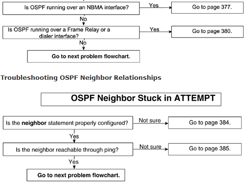
Problem: OSPF Neighbor Stuck in ATTEMPT
This problem is valid only for NMBA networks in which neighbor statements are defined. Stuck in ATTEMPT means that a router is trying to contact a neighbor by sending its Hello but hasn’t received any response. The state of ATTEMPT itself is not a problem because this is a normal state that a router goes through in NBMA mode; however, if a router is stuck in this state for a long time, it’s an indication of a problem. Chapter 8 discusses the ATTEMPT state in greater detail.
The most common possible causes of this problem are as follows:
- Misconfigured neighbor statement
- Unicast broken on NBMA
Figure 9-20 shows a network in which two routers are running OSPF. This network setup is used to produce a stuck in ATTEMPT problem.

shows the output of show ip ospf neighbor, which indicates that the neighbor is stuck in ATTEMPT. The neighbor ID field shows N/A, which means that this router doesn’t have any information about the neighbor—that’s why this field is showing N/A; otherwise, it would show the neighbor’s router ID.
Example 9-56 OSPF Neighbors Stuck in ATTEMPT State
R2#show ip ospf neighbor
Neighbor ID Pri State Dead Time Address Interface
N/A 0 ATTEMPT/DROTHER 00:01:57 131.108.1.1 Serial0
OSPF Neighbor Stuck in ATTEMPT—Cause: Misconfigured neighbor Statement
OSPF sends a unicast packet on NBMA interfaces if neighbor statements manually are configured under the router ospf configuration. This neighbor statement defines the destination IP address of the OSPF packet. If the neighbor statement is not correct, OSPF cannot send the packet to the right neighbor. It is very common to make a configuration mistake, so if the neighbor doesn’t come up after a while, check the neighbor statement either in the OSPF configuration or in the output of show ip ospf neighbor. If the neighbor shows in ATTEMPT state, this router is trying to contact a neighbor by sending the Hello packet, but it has not received any response from the neighbor.
Figure 9-21 shows the flowchart to follow to solve this problem.

Debugs and Verification
In Example 9-57, the output of show ip ospf neighbor indicates that the neighbor is stuck in ATTEMPT. The neighbor statement is configured, but the neighbor IP address is not correct. Instead of 131.108.1.1 (as shown in the Figure 9-20), it shows 131.108.1.11.
Example 9-57 show ip ospf neighbor Command Output Indicates That the Neighbor Is Stuck in ATTEMPT
R2#show ip ospf neighbor
Neighbor ID Pri State Dead Time Address Interface
N/A 0 ATTEMPT/DROTHER 00:01:57 131.108.1.11 Serial0
Example 9-58 shows the configuration of R2, indicating that the neighbor statement also is wrongly configured.
Example 9-58 R2’s Configuration Has an Incorrect neighbor Statement
R2#
router ospf 1
network 131.108.0.0 0.0.255.255 area 1
neighbor 131.108.1.11 priority 1
Solution
To fix this problem, configure the proper neighbor statement with the proper IP address. Example 9-59 shows the new configuration of R2 that fixes this problem.
Example 9-59 Configuring the Proper neighbor Statement on R2 to Correct the Problem
R2#
router ospf 1
network 131.108.0.0 0.0.255.255 area
neighbor131.108.1.1 priority 1
Example 9-60 shows the output of show ip ospf neighbor after fixing the problem.
Example 9-60 Verifying That the New neighbor Statement Has Resolved the Issue
R2#show ip ospf neighbor
Neighbor ID Pri State Dead Time Address Interface
131.108.2.1 1 FULL/DR 00:01:42 131.108.1.1 Serial0
OSPF Neighbor Stuck in ATTEMPT—Cause: Unicast Connectivity Is Broken on NBMA
OSPF sends unicast Hellos over NBMA interfaces if neighbor statements manually are con-figured. If the unicast connectivity is broken, OSPF will never form any adjacencies. OSPF tries to contact neighbors every Hello interval (that is, every 30 seconds) by default over NBMA interfaces. If it does not receive any reply from the neighbor, it will show that the neighbor is stuck in ATTEMPT. Many possible reasons can exist for broken unicast connectivity. You should consider the following causes for a broken unicast connectivity, assuming that Layer 2 is up:
- A wrong DLCI or VPI/VCI mapping exists in a Frame Relay or ATM switch, respectively.
- An access list is blocking the unicast.
- NAT is translating the unicast.
Figure 9-22 shows the flowchart to follow to solve this problem.

Debugs and Verification
Example 9-61 shows the output of a ping initiated from R2 to R1. The ping shows 100 percent failure. Because the ping uses ICMP and is a unicast packet, the failure indicates that the unicast connectivity is broken.
Example 9-61 ping Failure Indicates a Connectivity Problem
R2#ping 131.108.1.1
Type escape sequence to abort.
Sending 5, 100-byte ICMP Echos to 131.108.1.1, timeout is 2 seconds:
.....
Success rate is 0 percent (0/5)
R2#
Solution
As mentioned previously, the unicast broken connectivity could be the result of many factors. If it’s a wrong DLCI or VC mapping, be sure to check these mappings and correct those. If it’s the access list that is blocking the unicast connectivity, be sure to permit the necessary unicast IP address in the access list. Example 9-62 shows the output of show ip ospf neighbor after fixing the unicast connectivity problem.
Example 9-62 Verifying That Unicast Is Operational Again and That OSPF Is Forming Neighbors
R2#show ip ospf neighbor
Neighbor ID Pri State Dead Time Address Interface
131.108.2.1 1 FULL/DR 00:01:42 131.108.1.1 Serial0
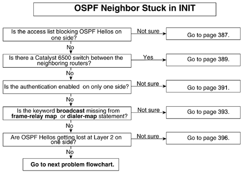
Problem: OSPF Neighbor Stuck in INIT
When a router receives an OSPF Hello from a neighbor, it sends the Hello packet by including that neighbor’s router ID in the Hello packet. If it doesn’t include the neighbor’s router ID, the neighbor will be stuck in INIT. This is an indication of a problem. The first packet that a router receives will cause the router to go into INIT state. At this point, it is not a problem, but if the router stays in this state for a long time, it’s an indication of a problem. It means that the neigh-bor router is not seeing Hellos sent by this router—that’s why it is not including the router ID of the router in its Hello packet. The network setup in Figure 9-20 is used here to discuss the stuck in INIT problem.
The most common possible causes of this problem are as follows:
- An access list on one side is blocking OSPF Hellos.
- Multicast capabilities are broken on one side (6500 switch problem).
- Authentication is enabled on only one side (virtual link example).
- The frame-relay map/dialer map statement on one side is missing the broadcast keyword.
- Hellos are getting lost on one side at Layer 2.
Example 9-63 shows the output of show ip ospf neighbor, which shows stuck in INIT.
Example 9-63 show ip ospf neighbor Command Output Indicates That R2’s Neighbor Is Stuck in INIT
R2#show ip ospf neighbor
Neighbor ID Pri State Dead Time Address Interface
131.108.2.1 1 INIT/- 00:00:33 131.108.1.1 Ethernet0
OSPF Neighbor Stuck in INIT—Cause: Access List on One Side Is Blocking OSPF Hellos
OSPF uses a multicast address of 224.0.0.5 for sending and receiving Hello packets. If an access list is defined on the interface and OSPF is enabled on that interface, this multicast address must be explicitly permitted in the access list; otherwise, it can produce problems such as stuck in INIT. The stuck in INIT problem occurs only if one side is blocking OSPF Hellos. If both sides are blocking OSPF Hellos, the output of show ip ospf neighbor returns an empty list.
Figure 9-23 shows the flowchart to follow to solve this problem.

Debugs and Verification
Example 9-64 shows the output of show access-list 101 and debug ip packet 101 detail on R1, where access list 101 is configured to see only the OSPF Hello packets between R1 and R2.
Example 9-64 debug Output Shows That OSPF Hellos Are Denied
R1#show access-list 101
Extended IP access list 101
permit ip 131.108.1.0 0.0.0.3 host 224.0.0.5 (8 matches)
R1#debug ip packet 101 detail
IP packet debugging is on (detailed) for access list 101
R1#
IP: s=131.108.1.1 (local), d=224.0.0.5 (Ethernet0), len 60, sending broad/multicast,
proto
=89
IP: s=131.108.1.2 (Ethernet0), d=224.0.0.5, len 82, access denied, proto=89
IP: s=131.108.1.1 (local), d=224.0.0.5 (Ethernet0), len 60, sending broad/multicast,
prot
=89
IP: s=131.108.1.2 (Ethernet0), d=224.0.0.5, len 82,access denied, proto=89
Example 9-65 shows the configuration of R1. Access list 100 on R1 is permitting only traffic destined for R1 and R2 interface addresses; it denies any other traffic, including OSPF Hellos.
Access list 101 on Router R1 is configured to limit the debug so that it will display only OSPF Hellos going across.
Example 9-65 Access List Configuration on R1 That Blocks OSPF Hellos
R1#
!
interface Ethernet0
ip address 131.108.1.1 255.255.255.0
ip access-group 100 in
!
access-list 100 permit ip any 131.108.1.0 0.0.0.255
Solution
To fix this problem, allow the OSPF Hellos in access list 100 on R1. The new line allows any packet source from 131.108.1.0–255 destined for OSPF multicast address of 224.0.0.5. Example 9-66 shows the modified access list on R1.
Example 9-66 Modified Access List on R1
R1#
access-list 100 permit ip any 131.108.1.0 0.0.0.255
access-list 100 permit ip 131.108.1.0 0.0.0.255 host 224.0.0.
Example 9-67 shows the output of show ip ospf neighbor after fixing the problem.
Example 9-67 show ip ospf neighbor Command Output Verifies That the Access List Now Permits OSPF Multicasts and OSPF Neighbors Are Formed
R2#show ip ospf neighbor
Neighbor ID Pri State Dead Time Address Interface
131.108.2.1 1 FULL/DR 00:00:39 131.108.1.1 Ethernet0
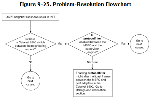
OSPF Neighbor Stuck in INIT—Cause: Multicast Capabilities Are Broken on One Side (6500 Switch Problem)
This is a specific situation that is valid only in the case of a Catalyst 6500 switch with the multilayer switch feature card (MSFC). The problem is that one side is sending OSPF Hellos that the other side does not receive. The network setup in Figure 9-24 shows how this can be a problem.

This situation is produced when the command set protocolfilter enabled is entered on the 6500 switch. By default, the protocol filter is disabled. Enabling this command begins altering the multicast frame to and from MSFC and port adapter within the FlexWan module of the 6500 switch. Figure 9-25 shows the flowchart to follow to solve this problem.
Debugs and Verification
Example 9-68 shows the output of show ip ospf neighbor. The neighbor is stuck in INIT, and the switch in the middle is 6500 with MSFC, as shown in Figure 9-24.
Example 9-68 OSPF Neighbor Stuck in INIT State
R2#show ip ospf neighbor
Neighbor ID Pri State Dead Time Address Interface
131.108.2.1 1 x INIT/- 00:00:33 131.108.1.1 FastEthernet0/0
Solution
To fix this problem, disable the protocol filter on 6500 switch as follows:
CAT6k(enable) set protocolfilter disable
Example 9-69 shows the OSPF neighbors in FULL state after fixing this problem.
Example 9-69 Verifying That the OSPF Neighbors Are Up After the Protocol Filter on the 6500 Switch Has Been Disabled
R2#show ip ospf neighbor
Neighbor ID Pri State Dead Time Address Interface
131.108.2.1 1 FULL/DR 00:00:33 131.108.1.1 FastEthernet0/0
OSPF Neighbor Stuck in INIT—Cause: Cause: Authentication Is Enabled Only on One Side
When authentication is used, it must be enabled on both sides; otherwise, one side will show the neighbor stuck in the INIT state. The router that has authentication enabled will reject all the nonauthenticated packets, and the adjacency will show stuck in INIT. The other side will not detect any problem because the authentication is turned on, so it will simply ignore the authentication in a packet and treat it as a normal packet.
Figure 9-26 shows the flowchart to follow to solve this problem.

Debugs and Verification
Example 9-70 shows the output of debug ip ospf adj on R2 indicating that Router R2 has plain-text authentication enabled but R1 is sending packets without any authentication. As a result, R2 rejects those packets. This is an example of plain-text authentication. In cases of MD5 authentication, the debug output will say we use type 2.
Example 9-70 debug ip ospf adj Command Output Indicates an Authentication Type Mismatch on the Neighboring Router
R2#debug ip ospf adj
OSPF adjacency events debugging is on
R2#
OSPF: Rcv pkt from 131.108.1.1, Ethernet0 : Mismatch Authentication type. Input packet
specified type 0, we use type 1
Example 9-71 shows the configuration of R2. The configuration shows that R2 is using plain-text authentication in area 1. This problem will reproduce with or without defining the authentication key under the interface. If the keys are not defined, the router uses a default key.
Example 9-71 R2 Uses Plain-Text Authentication in Area 1
R2#
router ospf 1
network 131.108.1.0 0.0.0.255 area 1
area 1 authentication
Solution
To fix this problem, enable authentication on both sides and define the authentication key on both sides. Example 9-72 shows the new configuration for both R1 and R2 that fixes this problem.
Example 9-72 Configuring Authentication on Both Routers to Resolve the Problem
R2#
!
interface Ethernet0
ip address 131.108.1.2 255.255.255.0
ip ospf authentication-key cisco
!
router ospf 1
network 131.108.1.0 0.0.0.255 area 1
area 1 authentication
_____________________________________________________________________________________
R1#
!
interface Ethernet0
ip address 131.108.1.1 255.255.255.0
ip ospf authentication-key cisco
!
router ospf 1
network 131.108.1.0 0.0.0.255 area 1
area 1 authenticatio
Example 9-73 shows the neighbor state after fixing this problem.
Example 9-73 show ip ospf neighbor Command Output Verifies That the Authentication Fix Has Resolved the Problem
R2#show ip ospf neighbor
Neighbor ID Pri State Dead Time Address Interface
131.108.2.1 1 FULL/DR 00:00:33 131.108.1.1 Ethernet0
Similar problems occur in a virtual link situation. When authentication is enabled on backbone routers, it is a very common mistake not to enable authentication on the router that is connected to two different areas. This router becomes a virtual ABR after creating a virtual link; therefore, authentication must be enabled for area 0 on that router even though area 0 is not manually configured on it.
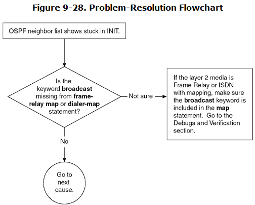
OSPF Neighbor Stuck in INIT—Cause: The frame-relay map/dialer-map Statement on One Side Is Missing the broadcast Keyword
OSPF uses a multicast address of 224.0.0.5 to send and receive OSPF Hellos. If one side is incapable of sending or receiving Hellos, the OSPF neighbor will be stuck in the INIT state. The important thing to note here is that only one side suffers from this multicast prob-lem. R1 sees the neighbor in INIT state but can see the neighbor Hellos without any problem. When R1 sends the Hello to R2, it never reaches R2 because Layer 2 is incapable of sending any broadcast or multicast packets. This is because of the lack of the broadcast keyword in frame-relay map statement on R1. A similar problem can occur in the case of ISDN or dialer interface when the dialer map statement is configured without the broadcast keyword.
Figure 9-27 shows the network setup for the discussion of this problem.

Figure 9-28 shows the flowchart to follow to solve this problem.
Debugs and Verification
The output of debug ip packet 100 detail in Example 9-74 indicates that the Hello packets generated from R1 are not getting across because of an encapsulation failure.
Example 9-74 Encapsulation Failure Is Preventing Hello Packets from Being Propagated from R1
R1#show access-list 100
Extended IP access list 100
permit ip 131.108.1.0 0.0.0.3 host 224.0.0.5 (8 matches)
R1#debug ip packet 100 detail
IP packet debugging is on (detailed) for access list 100
R1#
IP: s=131.108.1.2 (Serial0), d=224.0.0.5, len 64, rcvd 0, proto=89
IP: s=131.108.1.1 (local), d=224.0.0.5 (Serial0), len 68, sending broad/multicast,
proto=89
IP: s=131.108.1.1 (local), d=224.0.0.5 (Serial0), len 68, encapsulation failed,
proto=89
Example 9-75 shows the configuration of R1 and R2. The configuration shows that the broadcast keyword is missing from the frame-relay map statement on R1. R2, however, has the correct frame-relay map statement.
Example 9-75 Configurations for R1 and R2; R1 Omits the broadcast Keyword
R1#
interface Serial0
ip address 131.108.1.1 255.255.255.0
encapsulation frame-relay
frame-relay map ip 131.108.1.2 16
_____________________________________________________________________________________
R2#
interface Serial0
ip address 131.108.1.2 255.255.255.0
encapsulation frame-relay
frame-relay map ip 131.108.1.1 16 broadcast
Solution
To fix this problem, make sure that the broadcast keyword is configured in all frame-relay map or dialer-map statements. Example 9-76 shows the new configurations of R1 and R2 to fix the problem.
Example 9-76 Correcting the frame-relay map Statement on R1 to Include the broadcast Keyword
R1#
interface Serial0
ip address 131.108.1.1 255.255.255.0
encapsulation frame-relay
ip ospf network broadcast
frame-relay map ip 131.108.1.2 16 broadcast
_____________________________________________________________________________________
R2#
interface Serial0
ip address 131.108.1.2 255.255.255.0
encapsulation frame-relay
ip ospf network broadcast
frame-relay map ip 131.108.1.1 16 broadcast
Example 9-77 shows that OSPF adjacency is formed across the serial interface using Frame Relay encapsulation after fixing this problem.
Example 9-77 show ip ospf neighbor Command Output Indicates That the Problem Has Been Resolved
R2#show ip ospf neighbor
Neighbor ID Pri State Dead Time Address Interface
131.108.2.1 1 FULL/BDR 00:00:32 131.108.1.1 Serial0
OSPF Neighbor Stuck in INIT—Cause: Hellos Are Getting Lost on One Side at Layer 2
This situation happens when there is a problem on the Layer 2 media; for example, the Frame Relay switch is blocking the multicast traffic for some reason. When R1 sends the Hello, R2 never receives it. Because R2 never saw Hellos from R1, the neighbor list of R2 will be empty. However, R1 sees the Hellos from R2, which does not list R1 as a valid neighbor; so, R1 declares this neighbor in the INIT state.
Figure 9-29 shows the flowchart to follow to solve this problem.

Debugs and Verification
Example 9-78 shows the debug ip packet detail output on both R1 and R2. This debug is turned on against access list 100, which shows that R1 is sending and receiving OSPF Hellos but R2 is only sending and not receiving any OSPF Hellos.
Example 9-78 debug Output Shows That R2 Is Sending but Not Receiving Any OSPF Hellos from R1
R1#show access-list 100
Extended IP access list 100
permit ip 131.108.1.0 0.0.0.3 host 224.0.0.5 (8 matches)
R1#debug ip packet 100 detail
IP packet debugging is on (detailed) for access list 100
R1#
IP: s=131.108.1.2 (Serial0), d=224.0.0.5, len 64, rcvd 0, proto=89
IP: s=131.108.1.1 (local), d=224.0.0.5 (Serial0), len 68, sending broad/multicast,
proto=89
_____________________________________________________________________________________
R2#show access-list 100
Extended IP access list 100
permit ip 131.108.1.0 0.0.0.3 host 224.0.0.5 (8 matches)
R2#debug ip packet 100 detail
IP packet debugging is on (detailed) for access list 100
R1#
IP: s=131.108.1.1 (local), d=224.0.0.5 (Serial0), len 68, sending broad/multicast,
proto=89
IP: s=131.108.1.1 (local), d=224.0.0.5 (Serial0), len 68, sending broad/multicast,
proto=89
R1 keeps sending OSPF Hellos but never receives any Hellos from R2. This means that R2’s Hellos are getting lost in the middle because the debug shows that R2 is sending as well as receiving OSPF Hellos.
Solution
The debug is done on both sides, and it is clear that both sides are sending Hellos but R1 Hellos never get across. Most likely, the Frame Relay cloud or other Layer 2 medium is dropping this multicast packet. This also can be verified by using a sniffer on the wire.
The solution for this problem is to fix the Layer 2 multicast capabilities, which is out of the scope of this book. One possible workaround in this situation has the following steps:
Step 1. Change the network type on both sides to nonbroadcast.
Step 2. Configure the neighbor statement on one router.
Example 9-79 shows the new interface configuration that is used so that a neighbor statement can fix this problem. Basically, the interface has been defined as nonbroadcast, so a neighbor statement can be defined. When a neighbor statement is defined, OSPF sends a unicast Hello packet. This configuration always works when the multicast capabilities of any Layer 2 media are broken.
Example 9-79 Changing the Network Type on Both Sides to Nonbroadcast
R1#
interface Serial
ip address 131.108.1.1 255.255.255.0
encapsulation frame-relay
ip ospf network non-broadcast
frame-relay map ip 131.108.1.2 16 broadcast
_____________________________________________________________________________________
R2#
interface Serial0
ip address 131.108.1.2 255.255.255.0
encapsulation frame-relay
ip ospf network non-broadcast
frame-relay map ip 131.108.1.1 16 broadcast
Example 9-80 shows the OSPF configuration that configures the neighbor statement so that OSPF sends unicast Hello packets.
Example 9-80 Configuring neighbor Statement So That OSPF Sends a Unicast Hello
R1#
router ospf 1
network 131.108.1.0 0.0.0.255 area 1
neighbor 131.108.1.2
This solution is a workaround for the Layer 2 problem, but it doesn’t fix the original Layer 2 problem. By changing the network type to nonbroadcast, as done in Example 9-79, OSPF will send and receive Hellos as unicast instead of multicast. So, if any issues occur with multicast at Layer 2, changing the network type to nonbroadcast and configuring a neighbor statement causes OSPF to form neighbors on a medium whose multicast capabilities are broken.
Example 9-81 shows that the OSPF adjacency is formed across the serial interface using the neighbor command with a nonbroadcast network type.
Example 9-81 Verifying That Using a Nonbroadcast Network Type Resolves the OSPF Neighbor Stuck in INIT Caused by a Layer 2 Issue
R2#show ip ospf neighbor
Neighbor ID Pri State Dead Time Address Interface
131.108.2.1 1 FULL/DR 00:00:32 131.108.1.1 Serial0
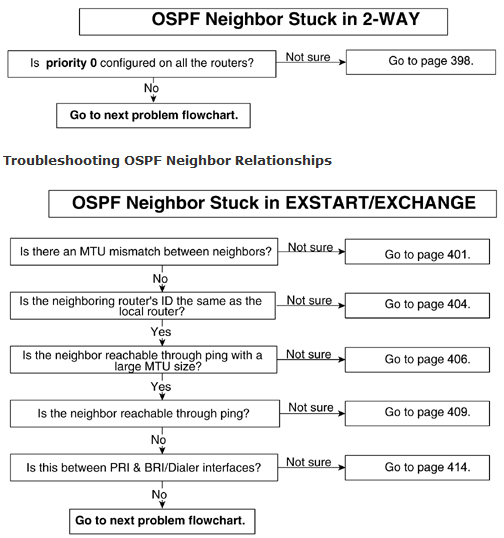
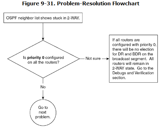
Problem: OSPF Neighbor Stuck in 2-WAY—Cause: Priority 0 Is Configured on All Routers
It is normal in broadcast media to have a 2-WAY state because not every router becomes adjacent on broadcast media. Every router enters into FULL state with the DR and the BDR.
In this example, there are only two routers on Ethernet; both are configured with priority 0. Priority 0 means that this router will not take part in DR/BDR election process. This configuration is useful when there are “low-end” routers on the segment and the desire is not to make those low-end routers DRs. For this purpose, you should configure priority 0. By default, the priority is set to 1. A router with the highest priority on a segment wins a DR election. If all priorities are kept to the default, the router with the highest router ID becomes the DR. For more information on DR and BDR election, refer to Chapter 8.
If all the routers on an Ethernet segment are configured with priority 0, no routers on the segment will be in FULL state with any other router. This creates problems. At least one router on the segment must have a priority that is not set to 0.
Figure 9-30 shows the network setup suffering from this problem.

Figure 9-31 shows the flowchart to follow to solve this problem.
Debugs and Verification
Example 9-82 shows the output of show ip ospf neighbor. No neighbors on this interface are in FULL state with each other.
Example 9-82 show ip ospf neighbor Command Output Determines That Neighbors Are in 2-WAY State with Each Other
R2#show ip ospf neighbor
Neighbor ID Pri State Dead Time Address Interface
131.108.2.1 0 2-WAY/DROTHER 00:00:32 131.108.1.1 Ethernet0
Example 9-83 shows that both R1 and R2 Ethernet interfaces are configured with priority 0.
Example 9-83 Priority Settings on Ethernet0 Interfaces of R1 and R2
R1#
interface Ethernet0
ip address 131.108.1.1 255.255.255.0
ip ospf priority 0
_____________________________________________________________________________________
R2#
interface Ethernet0
ip address 131.108.1.1 255.255.255.0
ip ospf priority 0
Solution
To fix this problem, remove the priority 0 command on at least one router so that router becomes a DR and forms a FULL adjacency. Example 9-84 shows the configuration change on R1 that fixes this problem.
Example 9-84 Removing priority 0 from R1 So That It Can Form FULL Adjacency with R1
R1#
interface Ethernet0
ip address 131.108.1.1 255.255.255.0
no ip ospf priority 0
Example 9-85 shows that after removing the priority 0 command on R1, the problem is fixed and OSPF forms an adjacency with its neighbor.
Example 9-85 Verifying That Removing priority 0 on R1 Has Fixed the Problem
R2#show ip ospf neighbor
Neighbor ID Pri State Dead Time Address Interface
131.108.2.1 1 FULL/DR 00:00:32 131.108.1.1 Ethernet0
Problem: OSPF Neighbor Stuck in EXSTART/EXCHANGE
This is an important state during the OSPF adjacency process. In this state, the router elects a master and a slave and the initial sequence number. The whole database also is exchanged during this state. If a neighbor is stuck in EXSTART/EXCHANGE for a long time, it is an indication of a problem. For more information on the EXSTART/EXCHANGE state, refer to Chapter 8.
The most common possible causes of this problem are as follows:
- Mismatched interface MTU
- Duplicate router IDs on neighbors
- Inability to ping across with more than certain MTU size
- Broken unicast connectivity because of the following:
- Wrong VC/DLCI mapping in Frame Relay/ATM switch
- Access list blocking the unicast
- NAT translating the unicast
- Network type of point-to-point between PRI and BRI/dialer
Figure 9-32 shows two routers running OSPF. This setup produces the stuck in EXSTART/EXCHANGE problem in OSPF.

shows the output of show ip ospf neighbor, which indicates that the neighbor is stuck in EXSTART/EXCHANGE.
Example 9-86 show ip ospf neighbor Command Output Indicates That a Neighbor Is Stuck in EXSTART/EXCHANGE
R2#show ip ospf neighbor
Neighbor ID Pri State Dead Time Address Interface
131.108.2.1 1 EXSTART/- 00:00:33 131.108.1.1 Serial0
OSPF Neighbor Stuck in EXSTART/EXCHANGE—Cause: Mismatched Interface MTU
OSPF sends the interface MTU in a database description packet. If there is a MTU mis-match, OSPF will not form an adjacency. The interface MTU option was added in RFC 2178. Previously, there was no mechanism to detect the interface MTU mismatch. This option was added in Cisco IOS Software Release 12.0.3 and later.
Figure 9-33 shows the flowchart to follow to solve this problem.

Debugs and Verification
Example 9-87 shows the output of the debug ip ospf adj command on R1, which indicates that the neighbor MTU is higher. As a result, OSPF can’t form an adjacency.
Example 9-87 debug ip ospf adj Command Output Indicates a Mismatched Interface MTU
R1#debug ip ospf adj
OSPF: Retransmitting DBD to 131.108.1.2 on Serial0.1
OSPF: Send DBD to 131.108.1.2 on Serial0.1 seq 0x1E55 opt 0x2 flag 0x7 len 32
OSPF: Rcv DBD from 131.108.1.2 on Serial0.1 seq 0x22AB opt 0x2 flag 0x7 len 32 mtu 1500
state EXSTART
OSPF: Nbr 131.108.1.2 has larger interface MTU
Example 9-88 shows the output of show ip interface on R1 and R2. The IP interface MTU on R1 is set to 1400 bytes; on R2, it is set to 1500 bytes. This creates an MTU mismatch problem.
Example 9-88 show ip interface Command Output on R1 and R2 Pinpoints the MTU Mismatch
R1#show ip interface serial 0.1
Serial0.1 is up, line protocol is up
Internet address is 131.108.1.1/24
Broadcast address is 255.255.255.255
MTU is 1400 bytes
_____________________________________________________________________________________
R2#show ip interface serial 0.1
Serial0.1 is up, line protocol is up
Internet address is 131.108.1.2/24
Broadcast address is 255.255.255.25
MTU is 1500 bytes
Solutions
In Cisco IOS Software Release 12.0.3 and later, if there is a MTU mismatch, Cisco IOS Software will indicate this in a debug message, as shown in Example 9-87. If R2’s MTU is smaller than R1’s, this message is not generated. Also, if R1 is not running Cisco IOS Software Release 12.0.3 or later, this message does not appear in the debug. The only way to detect this MTU mismatch is to check the interface configurations on both sides.
To correct this problem, make sure that the MTU is set to the same value on both sides. Example 9-89 shows the new configuration on R1 that fixes this problem.
Example 9-89 Setting the Same MTU Value on R1
R1#
interface Serial0.1 multipoint
ip address 141.108.10.3 255.255.255.248
mtu 1500
There is another situation that could lead to a MTU mismatch—when a router is connected through FDDI to a switch with the route switch module (RSM) blade in it. Figure 9-34 shows this setup.

The VLAN 1 interface is the virtual Ethernet interface with the MTU of 1500 bytes, while the FDDI interface on R2 has the MTU of 4470, as shown in Example 9-90.
Example 9-90 Configuration of RSM and R2 Shows MTU Mismatch
RSM#show interface vlan 1
Vlan1 is up, line protocol is up
Hardware is Cat5k RP Virtual Ethernet, address is 0030.f2c9.8338 (bia 0030.f2)
Internet address is 131.108.1.1/24
MTU 1500 bytes, BW 10000 Kbit, DLY 1000 usec,
_____________________________________________________________________________________
R2#show interface fddi 0
Fddi0 is up, line protocol is up
Hardware is DAS FDDI, address is 0000.0c17.acbf (bia 0000.0c17.acbf)
Internet address is 131.108.1.2/24
MTU 4470 bytes, BW 100000 Kbit, DLY 100 usec, rely 255/255, load 1/255
This is a normal setup in a Catalyst switch environment. When a packet is received on a switch FDDI port, it goes across the switch backplane to the slot where the RSM is installed. The conversion/fragmentation from FDDI to Ethernet happens at the switch level.
With the MTU mismatch-detection feature, these two routers never form an adjacency. For this particular situation, an interface-level command, ip ospf mtu-ignore, was added in Cisco IOS Software Release 12.1.3 and later. This command ignores the FDDI MTU and forms an adjacency in this particular situation. This command must never be used in any other situation because MTU mismatch detection is important for troubleshooting purposes. To use this command, apply it under the interface. In this example, it should be applied under the VLAN 1 interface.
Example 9-91 shows the output of show ip ospf neighbor after fixing the MTU problem.
Example 9-91 Verifying That the MTU Mismatch Has Been Resolved
R2#show ip ospf neighbor
Neighbor ID Pri State Dead Time Address Interface
131.108.2.1 1 FULL/DR 00:00:32 131.108.1.1 Fddi0
OSPF Neighbor Stuck in EXSTART/EXCHANGE—Cause: Duplicate Router IDs on Neighbors
When OSPF sends a DBD packet to elect a master and a slave, the router with the highest router ID becomes the master. This happens in the EXSTART process. If there is any problem with election, the router will be stuck in the EXSTART/EXCHANGE state.
Figure 9-35 shows the flowchart to follow to solve this problem.

Debugs and Verification
Example 9-92 shows the output of show ip ospf neighbor on R1 indicating that the neighbor is stuck in the EXSTART state.
Example 9-92 show ip ospf neighbor Command Output Shows That R1 Is in the EXSTART State
R2#show ip ospf neighbor
Neighbor ID Pri State Dead Time Address Interface
131.108.2.1 1 EXSTART/- 00:00:33 131.108.1.1 Serial0
Example 9-93 shows the output of debug ip ospf adj. If the DBD packets keep retransmitting and the flag value remains 7, this is an indication of a problem. This means that neither router can determine which will be the master and which will be a slave. A flag is a 3-bit value that comes from the DBD packet format and represents the I, M, and MS bits. The value of the flag is set to 7 in the first DBD—this means that the I, M, and MS bit values are set to 1. For more information on the I, M, and MS bits, refer to Chapter 8.
Example 9-93 debug Output Shows That a Master and Slave Are Not Being Formed
R2#debug ip ospf adj
OSPF: Retransmitting DBD to 131.108.2.1 on Serial0
OSPF: Send DBD to 131.108.2.1 on Serial0 seq 0x793 opt 0x2 flag 0x7 len 32
OSPF: Rcv DBD from 131.108.2.1 on Serial0 seq 0x25F7 opt 0x2 flag 0x7 len 32 mtu 0 state
EXSTART
OSPF: First DBD and we are not SLAVE
Example 9-94 shows the output of show ip ospf interface serial0 on R2, which displays the router ID as 131.108.2.1—the same as the neighbor’s. This prevents the election of master and slave.
Example 9-94 Router ID of R2 Is Same as Neighbor R1’s
R2#show ip ospf interface serial 0
Serial0 is up, line protocol is up
Internet Address 131.108.1.2/24, Area 1
Process ID 1, Router ID 131.108.2.1, Network Type POINT_TO_POINT, Cost: 64
Solution
Example 9-93 shows that R2 is sending a DBD packet with a flag of 7, saying, “I am the master.” R2 also receives a DBD from R1 saying, “I am the master.” R2 compares R1’s router ID and sees that it is not higher than its own, so it sends the DBD packet to R1 saying, “I am the master.” So, both routers keep fighting for the master status and the router gets stuck in the EXSTART state.
To solve this problem, carefully review the neighbor router ID and the local router ID to see if they are exactly the same. If so, you must change the router ID for one of the routers and restart the OSPF process so that it can take effect.
NOTE
Cisco IOS Software Release 12.0 and later provide a warning message, OSPF-3-DUP_RTRID, that warns if there is a duplicate router ID.
Example 9-95 shows the output of show ip ospf neighbor after this problem is fixed.
Example 9-95 Verifying That the Duplicate Router ID Problem Has Been Fixed and an OSPF Adjacency Can Be Established
R2#show ip ospf neighbor
Neighbor ID Pri State Dead Time Address Interface
131.108.2.1 1 FULL/- 00:00:32 131.108.1.1 Serial0
OSPF Neighbor Stuck in EXSTART/EXCHANGE—Cause: Can’t Ping Across with More Than Certain MTU Size
When OSPF begins forming an adjacency with its neighbor, it goes through several states. In EXSTART state, OSPF determines which will be the master and which will be the slave. After the routers decided this, they start exchanging the LSA header in the form of DBD packets. If the database is huge, OSPF uses the interface MTU and tries to send as much data as possible up to the limit of the interface MTU. If there is a problem with Layer 2 accepting large packets that are within the interface MTU range, the OSPF adjacency will be stuck in the EXCHANGE state.
Figure 9-36 shows the network setup that reproduces this problem. The Layer 2 medium intentionally is not shown in this figure because this problem can happen in any Layer 2 media.

shows the output of show ip ospf neighbor on R2, which is stuck in the EXCHANGE state with R1 on the serial link. This means that the master and slave negotiation already has taken place.
Example 9-96 show ip ospf neighbor Command Output Indicates an EXSTART Problem
R2#show ip ospf neighbor
Neighbor ID Pri State Dead Time Address Interface
131.108.2.1 1 EXCHANGE/- 00:00:46 131.108.1.2 Serial0/0
Figure 9-37 shows the flowchart to follow to solve this problem.

Debugs and Verification
Example 9-97 shows the output of debug ip ospf adj. The debug shows that R2 keeps retrans-mitting the DBD packets every 5 seconds, which is a default, and is not receiving any reply. Also note that the length of this packet is 1274 and the flag value is 3; this means that R2 is a master. Recall from the previous problem that a flag of 3 means that the M and MS bits are set.
Example 9-97 debug ip ospf adj Command Output Shows the DBD Packet Transmission History
R2#debug ip ospf adj
OSPF: Send DBD to 131.108.2.1 on Serial0 seq 0x793 opt 0x2 flag 0x3 len 1274
OSPF: Retransmitting DBD to 131.108.2.1 on Serial0
OSPF: Send DBD to 131.108.2.1 on Serial0 seq 0x793 opt 0x2 flag 0x3 len 1274
OSPF: Retransmitting DBD to 131.108.2.1 on Serial0
OSPF: Send DBD to 131.108.2.1 on Serial0 seq 0x793 opt 0x2 flag 0x3 len 1274
OSPF: Retransmitting DBD to 131.108.2.1 on Serial0
OSPF: Send DBD to 131.108.2.1 on Serial0 seq 0x793 opt 0x2 flag 0x3 len 1274
OSPF: Retransmitting DBD to 131.108.2.1 on Serial0
Example 9-98 shows the output of normal and extended pings from R1 to R2. When R1 pings R2 with an MTU equal to or greater than 1200, the ping never reaches the other side. This indicates a problem at Layer 2.
Example 9-98 Normal Ping Is Successful and Ping with 1,200 Fails
R1#ping 131.108.1.2
Type escape sequence to abort.
Sending 5, 100-byte ICMP Echos to 131.108.1.2, timeout is 2 seconds:
!!!!!
Success rate is 100 percent (5/5), round-trip min/avg/max = 1/1/1 ms
R1#
R1#ping ip
Target IP address: 131.108.1.2
Repeat count [5]:
Datagram size [100]: 1200
Timeout in seconds [2]:
Extended commands [n]:
Sweep range of sizes [n]:
Type escape sequence to abort.
Sending 5, 1200-byte ICMP Echos to 131.108.1.2, timeout is 2 seconds:
.....
Success rate is 0 percent (0/5)
R1#
Solution
The problem is actually with Layer 2. R1 can ping R2 when using a 100-byte datagram, but the ping starts failing when the datagram size is greater than 1200 bytes.
To solve this problem, fix the Layer 2 issue. One way to narrow this problem is to connect the two devices directly instead of going through switches and so forth, to see whether the problem is with the Layer 2 devices or with the router itself. If connecting routers back to back doesn’t fix the problem, there is a possibility of bad hardware. Most times, it turns out to be a problem in the middle—for example, a LAN switch or a telco cloud.
Depending upon the media, there are several recommendations:
- In the case of a LAN medium
- Check the MTU size defined in the switch configuration for this medium.
- Try using a different port.
- In the case of a WAN medium
- If you are the WAN cloud provider, check at which hop it fails.
- If you are getting a circuit from a telco, request that the WAN cloud in the middle be checked to see where it fails.
OSPF Neighbor Stuck in EXSTART/EXCHANGE—Cause: Unicast Connectivity Is Broken
When OSPF routers begin exchanging database information with each other, they send a unicast packet to each other in EXSTART/EXCHANGE state. This happens only if the network type is not a point-to-point link. In cases of a point-to-point link, OSPF sends all multicast packets. If unicast connectivity is broken, OSPF neighbor remains in EXSTART state.
Figure 9-38 shows the flowchart to follow to solve this problem.

Debugs and Verification
Example 9-99 shows the output of a ping from R1 to R2. The output shows that a ping packet with 100-byte datagrams fails.
Example 9-99 Ping Failure Shows That Unicast Connectivity Is Broken
R1#ping 131.108.1.2
Type escape sequence to abort.
Sending 5, 100-byte ICMP Echos to 131.108.1.2, timeout is 2 seconds:
.....
Success rate is 0 percent (0/5)
R1#
Solutions
This ping failure could occur for several reasons, including the following:
The wrong DLCI or VPI/VCI mapping exists in a Frame Relay or ATM switch, respectively.
- An access list is blocking the unicast.
- NAT is translating the unicast.
Wrong DLCI or VPI/VCI Mapping
In cases of Frame Relay or ATM, this is a very common problem. The packet will be lost in the Frame Relay or ATM cloud. To further verify that this is the case, turn on debug ip packet detail with the access list on both routers.
Example 9-100 shows the output of debug ip packet detail on both R1 and R2, indicating that the ICMP packet is being sent into the Frame Relay cloud but nothing is coming back.
Example 9-100 debug ip packet detail Command Output Indicates Successful ICMP Packet Transmission but No Receipt
R1#show access-list 100
Extended IP access list 100
permit ip 131.108.1.0 0.0.0.255 131.108.1.0 0.0.0.255 (10 matches)
R1#debug ip packet detail 100
R1#ping 131.108.1.2
Type escape sequence to abort.
Sending 5, 100-byte ICMP Echos to 131.108.1.2, timeout is 2 seconds:
.....
Success rate is 0 percent (0/5)
IP: s=131.108.1.1 (local), d=131.108.1.2 (Serial0), len 100, sending
ICMP type=8, code=0
IP: s=131.108.1.1 (local), d=131.108.1.2 (Serial0), len 100, sending
ICMP type=8, code=0
IP: s=131.108.1.1 (local), d=131.108.1.2 (Serial0), len 100, sending
ICMP type=8, code=0
IP: s=131.108.1.1 (local), d=131.108.1.2 (Serial0), len 100, sending
ICMP type=8, code=0
IP: s=131.108.1.1 (local), d=131.108.1.2 (Serial0), len 100, sending
ICMP type=8, code=0
R1#
_____________________________________________________________________________________
R2#show access-list 100
Extended IP access list 100
permit ip 131.108.1.0 0.0.0.255 131.108.1.0 0.0.0.255 (10 matches)
R2#debug ip packet detail 100
R2#ping 131.108.1.1
Type escape sequence to abort.
Sending 5, 100-byte ICMP Echos to 131.108.1.1, timeout is 2 seconds:
.....
Success rate is 0 percent (0/5)
IP: s=131.108.1.2 (local), d=131.108.1.1 (Serial0), len 100, sending
ICMP type=8, code=0
IP: s=131.108.1.2 (local), d=131.108.1.1 (Serial0), len 100, sending
ICMP type=8, code=0
IP: s=131.108.1.2 (local), d=131.108.1.1 (Serial0), len 100, sending
ICMP type=8, code=0
IP: s=131.108.1.2 (local), d=131.108.1.1 (Serial0), len 100, sending
ICMP type=8, code=0
IP: s=131.108.1.2 (local), d=131.108.1.1 (Serial0), len 100, sending
ICMP type=8, code=0
R2#
To solve this problem, the telephone carrier should be contacted to determine whether any such thing has happened. There is a slight chance that the problem could be with the router itself and that it is dropping the packet. Any other problems will appear in the debug messages. Problems such as the wrong Frame Relay mapping within the router produce “encapsulation failure” messages in the debug output.
Access List Blocking the Unicast
If an access list is configured on a router, make sure that it’s not blocking the unicast packet. Example 9-101 shows the output of debug ip packet detail 100 on R2, which shows that the unicast is being blocked. Access list 101 shows that only the multicast packets of OSPF are allowed and that unicast packets from the 131.108.1.0 address are denied because there is an implicit deny at the end of each access list.
Example 9-101 Revealing That the Unicast Connection Is Being Blocked
R1#show access-list 100
Extended IP access list 100
permit ip 131.108.1.0 0.0.0.255 131.108.1.0 0.0.0.255
R1#show access-list 101
Extended IP access list 101
permit ip 141.108.10.0 0.0.0.255 any
permit ip 141.108.20.0 0.0.0.255 any
permit ip 141.108.30.0 0.0.0.255 any
permit ip 131.108.1.0 0.0.0.255 host 224.0.0.5
R1#debug ip packet 100 detail
IP packet debugging is on (detailed) for access list 100
R1#
IP: s=131.108.1.2 (Serial0.2), d=131.108.1.1, len 100, access denied
ICMP type=8, code=0
IP: s=131.108.1.1 (local), d=131.108.1.2 (Serial0.2), len 56, sending
ICMP type=3, code=13
R1#
IP: s=131.108.1.2 (Serial0.2), d=131.108.1.1, len 100, access denied
ICMP type=8, code=0
IP: s=131.108.1.1 (local), d=131.108.1.2 (Serial0.2), len 56, sending
ICMP type=3, code=13
R1#
IP: s=131.108.1.2 (Serial0.2), d=131.108.1.1, len 100, access denied
ICMP type=8, code=0
IP: s=131.108.1.1 (local), d=131.108.1.2 (Serial0.2), len 56, sending
ICMP type=3, code=13
R1#
Example 9-101 clearly shows that the packet is being rejected because of the access list. All access lists have an implicit deny at the end of the list, so they also deny any packet not explicitly permitted (in this case, unicast packets). This causes OSPF to get stuck in the EXCHANGE state.
To solve this problem, modify access list 101 so it allows the unicast packets. Example 9-102 shows the modified access list that will solve the problem.
Example 9-102 Modifying an Access List to Permit Unicast Packets
R1#show access-list 101
Extended IP access list 101
permit ip 141.108.10.0 0.0.0.255 any
permit ip 141.108.20.0 0.0.0.255 any
permit ip 141.108.30.0 0.0.0.255 any
permit ip 131.108.1.0 0.0.0.255 host 224.0.0.5
permit ip 131.108.1.0 0.0.0.255 131.108.1.0 0.0.0.255
NAT Is Translating the Unicast
This is another common problem that occurs when NAT is configured on the router. If NAT is misconfigured, it will start translating the unicast packet coming toward it, which will break the unicast connectivity. Example 9-103 shows that R1 is configured with NAT. The outside inter-face of R1 is Serial 0.2, which connects to R2. Figure 9-39 shows R1 and R2 connected to each other, with R1 running NAT.

When R2 sends a unicast packet to R1, R1 tries to translate that packet and R2 never receives the ping reply. The main thing to watch for is the access list in NAT. If the access list is permitting everything, this problem will occur. Example 9-98 shows the NAT configuration on R1.
Example 9-103 NAT Configuration Resulting in Unicast Packets Being Translated
R1#
interface Ethernet 0
ip nat outside
!
ip nat inside source list 1 interface Serial0.2 overload
!
access-list 1 permit any
To solve this problem, change access list 1 and permit only those IP address that require translation. Example 9-104 shows the correct access list that solves the problem. The access list could be different from network to network. The whole idea is that the access list permit statement should not cover the neighbor’s IP address. In Example 9-104, only the inside network 10.0.0.0/8 is permitted. This means that R1 will no longer translate the packets belonging to the 131.108.1.0 network.
Example 9-104 Correcting the Access List to Solve the Unicast Connectivity Problem
R1#
interface Ethernet 0
ip address 131.108.1.1 255.255.255.0
ip nat outside
!
ip nat inside source list 1 interface Serial0.2 overload
!
access-list 1 permit 10.0.0.0 0.255.255.255
Example 9-105 shows the output of show ip ospf neighbor, which shows that OSPF neighbors are in the FULL state after fixing the unicast problem.
Example 9-105 Verifying That the Unicast Issue Has Been Resolved
R2#show ip ospf neighbor
Neighbor ID Pri State Dead Time Address Interface
131.108.2.1 1 FULL/- 00:00:32 131.108.1.1 Ethernet0
OSPF Neighbor Stuck in EXSTART/EXCHANGE—Cause: Network Type Is Point-to-Point Between PRI and BRI/Dialer
The network type on a PRI interface is point-to-point. This causes OSPF to send multicast packets even after the 2-WAY state. If only one BRI comes up as an OSPF neighbor, it will work fine. However, when multiple BRIs try to form an adjacency with the PRI, the PRI will complain because its network type is point-to-point. Because all OSPF packets are sent as multicast on a point-to-point link, the PRI receives DBD packets from multiple BRI neighbors, and this causes all the neighbors to get into the EXSTART/EXCHANGE state.
Figure 9-40 shows a network setup that produces this problem. R1 has a PRI, and both R2 and R3 dial into this PRI. This creates a problem in OSPF because the network type is point-to-point.

shows the output of show ip ospf neighbor on R1. R2 and R3 both are stuck in the EXSTART state, with R1 on an ISDN link. If the output shows neighbors in the EXSTART state, for a long time, it is an indication of a problem.
Example 9-106 PRI Neighbors Are Stuck in EXSTART State
R1#show ip ospf neighbor
Neighbor ID Pri State Dead Time Address Interface
131.108.1.2 1 EXSTART/- 00:00:38 131.108.1.2 Serial0/0:23
131.108.1.3 1 EXSTART/- 00:00:32 131.108.1.3 Serial0/0:23
Figure 9-41 shows the flowchart to follow to solve this problem.

Debugs and Verification
Example 9-107 shows the output of show ip ospf interface bri0 on R2 indicating that the network type is point-to-point.
Example 9-107 Verifying the Network Type on R2’s bri0 Interface
R2#show ip ospf interface bri0
BRI0 is up, line protocol is up (spoofing)
Internet Address 131.108.1.2/24, Area 2
Process ID 1, Router ID 131.108.1.2, Network Type POINT_TO_POINT, Cost: 1562
Transmit Delay is 1 sec, State POINT_TO_POINT,
Timer intervals configured, Hello 10, Dead 40, Wait 40, Retransmit 5
Hello due in 00:00:06
index 1/1, flood queue length 0
Next 0x0(0)/0x0(0)
Last flood scan length is 1, maximum is 1
Last flood scan time is 0 msec, maximum is 0 msec
Neighbor Count is 1, Adjacent neighbor count is 0
Suppress hello for 0 neighbor(s)
Example 9-108 shows the output of debug ip ospf adj on R2. The debug shows that R2 is receiving two different DBD packets on a point-to-point network type. The problem is that when R1 sends the DBD packets to R2 and R3, it sends them as multicasts because the network type is defined as point-to-point. In point-to-point networks, all OSPF packets are sent as multicast. This causes R2 to receive DBD packets destined for R3, and vice versa.
When R2 receives a DBD packet, it complains because the DBD packet’s sequence number and the flags are different. This causes R2 to go back into the EXSTART state. This cycle keeps repeating.
Example 9-108 debug Output Showing That R2 Is Receiving R3’s DBD Packets, Which Causes Problems
R2#debug ip ospf adj
Send DBD to 131.108.1.1 on BRI0 seq 0xB41 opt 0x42 flag 0x7 len 32
Rcv DBD from 131.108.1.1 on BRI0 seq 0x1D06 opt 0x42 flag 0x7 len 32 mtu 1500 state
EXSTART
First DBD and we are not SLAVE
Rcv DBD from 131.108.1.1 on BRI0 seq 0xB41 opt 0x42 flag 0x2 len 92 mtu 1500 state
EXSTART
NBR Negotiation Done. We are the MASTER
Send DBD to 131.108.1.1 on BRI0 seq 0xB42 opt 0x42 flag 0x3 len 92
Database request to 131.108.1.1
sent LS REQ packet to 131.108.1.1, length 12
Rcv DBD from 131.108.1.1 on BRI0 seq 0x250 opt 0x42 flag 0x7 len 32 mtu 1500 state
EXCHANGE
EXCHANGE - inconsistent in MASTER/SLAVE
Bad seq received from 131.108.1.1 on BRI0
Send DBD to 131.108.1.1 on BRI0 seq 0x2441 opt 0x42 flag 0x7 len 32
Rcv DBD from 131.108.1.1 on BRI0 seq 0x152C opt 0x42 flag 0x2 len 92 mtu 1500 state
EXSTART
Unrecognized dbd for EXSTART
Rcv DBD from 131.108.1.1 on BRI0 seq 0xB42 opt 0x42 flag 0x0 len 32 mtu 1500 state
EXSTART
Unrecognized dbd for EXSTART
Solution
To solve this problem, change the network type of PRI and BRI to point-to-multipoint. Example 9-109 shows the interface-level command to change the network type to point-to-multipoint, followed by the output of show ip ospf interface on R2.
Example 9-109 Verifying the Network Type on R2’s bri0 Interface
R2#
interface BRI0
ip ospf network point-to-multipoint
R2#show ip ospf interface bri0
BRI0 is up, line protocol is up (spoofing)
Internet Address 131.108.1.2/24, Area 2
Process ID 1, Router ID 131.108.1.2, Network Type POINT_TO_MULTIPOINT, Cost: 1562
Transmit Delay is 1 sec, State POINT_TO_MULTIPOINT,
Timer intervals configured, Hello 30, Dead 120, Wait 120, Retransmit 5
Hello due in 00:00:06
index 1/1, flood queue length 0
Next 0x0(0)/0x0(0)
Last flood scan length is 1, maximum is 1
Last flood scan time is 0 msec, maximum is 0 msec
Neighbor Count is 1, Adjacent neighbor count is 1
Suppress hello for 0 neighbor(s)
This change must be made on all the routers connected to the ISDN cloud. Changing the net-work type to point-to-multipoint forces OSPF to send a unicast packet for DBDs instead of a multicast after 2-WAY state, so the packet destined for R3 never reaches R2.
Problem: OSPF Neighbor Stuck in LOADING
This is a rare problem in OSPF neighbor relationships. When a neighbor is stuck in the LOADING state, the local router has sent a link-state request packet to the neighbor requesting an outdated or missing LSA and is waiting for an update from its neighbor. If a neighbor doesn’t reply or a neighbors’ reply never reaches the local router, the router will be stuck in the LOADING state.
The most common possible causes of this problem are as follows:
- Mismatched MTU
- Corrupted link-state request packet
Figure 9-42 shows a network with two routers running OSPF, with R1 experiencing a stuck in LOADING problem.

shows the output of show ip ospf neighbor indicating that R2’s neighbor is stuck in LOADING.
Example 9-110 show ip ospf neighbor Command Output Indicates Neighbor State—LOADING, in This Case
R2#show ip ospf neighbor
Neighbor ID Pri State Dead Time Address Interface
131.108.2.1 1 LOADING/- 00:00:37 131.108.1.1 Serial0
OSPF Neighbor Stuck in LOADING—Cause: Mismatched MTU Size
This is a unique problem that happens when an MTU mismatch occurs. If the MTUs are not the same across the link, this problem occurs. Specifically, if a neighbor’s MTU is greater than the local router’s, the neighbor sends a large MTU packet as a link-state update. This packet never reaches the local router; as a result, the neighbor gets stuck in the LOADING state.
Figure 9-42 shows the flowchart to follow to solve this problem.

Debugs and Verification
Example 9-111 shows the interface configurations on both R1 and R2. Both configurations show the MTU value different from each other’s.
Example 9-111 R1 and R2 Configurations Have Different MTU Values
R2#show interface Serial0
Serial0/0 is up, line protocol is up
Hardware is PQUICC with Fractional T1 CSU/DSU
MTU 2048 bytes, BW 256 Kbit, DLY 20000 usec,
_____________________________________________________________________________________
R1#show interface ATM4/0/0
ATM4/0/0 is up, line protocol is up
Hardware is cyBus ATM
MTU 4470 bytes, sub MTU 4470, BW 155520 Kbit, DLY 80 usec,
Example 9-112 shows the Cisco IOS Software release that both R1 and R2 are running. Because R2 is running 11.3(10)T, which is lower than 12.0.3, it fails to detect the mismatched MTU. The MTU mismatch detection was added in RFC 2178 and was implemented in Cisco IOS Software Release 12.0.3 and later.
Example 9-112 Verifying Cisco IOS Software Releases Used on R1 and R2
R2#show version
Cisco Internetwork Operating System Software
IOS (tm) C2600 Software (C2600-I-M), Version 11.3(10)T, RELEASE SOFTWARE (fc1)
Copyright (c) 1986-1999 by cisco Systems, Inc.
_____________________________________________________________________________________
R1#show version
Cisco Internetwork Operating System Software
IOS (tm) RSP Software (RSP-JSV-M) , Version 12.0(7)T, RELEASE SOFTWARE (fc2)
Copyright (c) 1986-1999 by cisco Systems, Inc.
Example 9-113 shows the output of debug ip ospf adj on R2. The debugs show that R2 continually is retransmitting the DBD packet to R1, but R1’s reply never makes it to R2 because the packet is too large.
Example 9-113 debug ip ospf adj Command Output on R2 Shows the Transmission History of DBD Packets to R1
R2#debug ip ospf adj
OSPF adjacency events debugging is on
R2#
OSPF: Retransmitting request to 131.108.2.1 on Serial0
OSPF: Database request to 131.108.2.1
OSPF: sent LS REQ packet to 131.108.1.1, length 12
OSPF: Retransmitting request to 131.108.2.1 on Serial0
Solution
In this particular case, R2 is running Cisco IOS Software Release 11.3.10T, which does not support MTU mismatch detection. R1 is running Cisco IOS Software Release 12.0.7T, which does support MTU mismatch detection. R1 detects MTU mismatches only when R2’s MTU is higher than R1’s; otherwise, it does not complain. In other words, MTU mismatch detection is valid only for a neighbor with an MTU higher than that of the local router.
In this case, R2’s MTU is 2048, so even though R1 is running Cisco IOS Software code with MTU mismatch detection, R1 cannot detect an MTU mismatch because R2’s MTU is lower than R1’s.
When R2 sends the LS request packet for the new instance of the LSAs, R1 replies with an LSA that exceeds 2048, so R2 never gets that packet because it is too large. To fix this problem, make sure that the MTUs on both sides match. To change the MTU on an interface (in this case, R2’s Serial 0 interface), enter the following interface-level command:
interface serial 0
mtu 4470
Example 9-114 shows the output of show ip ospf neighbor, indicating that OSPF neighbors are in the FULL state after fixing the unicast problem.
Example 9-114 Verifying That OSPF Forms Neighbor After Fixing the MTU Problem
R2#show ip ospf neighbor
Neighbor ID Pri State Dead Time Address Interface
131.108.2.1 1 FULL/- 00:00:32 131.108.1.1 Serial0
OSPF Neighbor Stuck in LOADING—Cause: Link-State Request Packet Is Corrupted
When a link-state request packet is corrupted, the neighbor discards the packet and the local router never receives the response from the neighbor. This causes the OSPF neighbor to be stuck in the LOADING state.
Link-state request packets usually become corrupted because of the following reasons:
- A device between the neighbors, such as a switch, is corrupting the packet.
- The sending router’s packet is invalid. In this case, either the sending router’s interface is bad or the error is caused by a software bug.
- The receiving router is calculating the wrong checksum. In this case, either the receiving router’s interface is bad or the error is caused by a software bug. This is the least likely cause of this error message.
Figure 9-44 shows the flowchart to follow to solve this problem.

Debugs and Verification
Example 9-115 shows the log messages on R2 indicating that R2 is receiving an OSPF packet with a bad checksum. This is a sign of packet corruption.
Example 9-115 Logs Show OSPF Received Bad Packets
R2#show log
%OSPF-4-ERRRCV: Received invalid packet: Bad Checksum from 131.108.1.1, Serial0
%OSPF-4-ERRRCV: Received invalid packet: Bad Checksum from 131.108.1.1, Serial0
Example 9-116 shows that R2 is retransmitting the LS request packet and is not getting any replies because the replies are getting corrupted.
Example 9-116 R2 Is Not Receiving Replies to Its Link-State Request Packets Because of Packet Corruption
R2#debug ip ospf adj
OSPF adjacency events debugging is on
R2#
OSPF: Retransmitting request to 131.108.2.1 on Serial0
OSPF: Database request to 131.108.2.1
OSPF: sent LS REQ packet to 131.108.1.1, length 12
OSPF: Retransmitting request to 131.108.2.1 on Serial0
Solution
Most of the time, this problem is fixed by replacing hardware. This could be a simple bad port on the switch or a bad interface card on the sending/receiving router.
Example 9-117 shows the output of show ip ospf neighbor indicating that OSPF neighbors are in the FULL state after fixing the corrupt link-state request packet problem.
Example 9-117 Verifying That the Corrupt Link-State Request Packet Problem Has Been Resolved, Allowing an OSPF Adjacency to Form
R2#show ip ospf neighbor
Neighbor ID Pri State Dead Time Address Interface
131.108.2.1 1 FULL/- 00:00:32 131.108.1.1 Serial0