Troubleshooting Load-Balancing Scenarios in Small BGP Networks
Problem: Load Balancing and Managing Outbound Traffic from a Single Router When Dual Homed to Same ISP—Cause: BGP Installs Only One Best Path in the Routing Table
In multihomed scenarios, a common concern that enterprise network operators face is improperly utilizing the external links going to the ISP. Typically, enterprise customers dual-home to either the same or different ISPs to load-share outgoing and incoming traffic.
Figure 15-41 shows a simple setup of R1 of AS 109 dual homed to same ISP AS 110 at R2 and R3. Both R2 and R3 are advertising prefix 100.100.100.0/24 to R1. Ideally, R1 should load-share traffic destined for prefix 100.100.100.0/24, but, by default, this does not happen and only one of the many paths available is used.

BGP selects only a single best route for a prefix out of many alternate paths. This is the default behavior governed by RFC 1771. R1 will have two paths for prefix 100.100.100.0/24—one from R2 and the other from R3. R1 will go through its BGP best-path calculation and will pick and install one route in the routing table.
Figure 15-42 shows the flowchart to follow to resolve this problem.

Debugs Verification
Example 15-80 shows output in R1 receiving two paths for prefix 100.100.100.0/24 but installing only one.
Example 15-80 Output of R1 Having Multiple Paths for 100.100.100.0/24 but Installing Only One in Its Routing Table
R1#show ip bgp 100.100.100.0
BGP routing table entry for 100.100.100.0/24, version 2
Paths: (2 available, best #2)
Not advertised to any peer
110
141.108.1.3 from 141.108.1.3 (1.2.1.1)
Origin IGP, metric 0, localpref 100, valid, external
110
141.108.1.1 from 141.108.1.1 (141.108.6.1)
Origin IGP, metric 0, localpref 100, valid, external, best
R1#show ip route 100.100.100.0
Routing entry for 100.100.100.0/24
Known via "bgp 109", distance 20, metric 0
Tag 110, type external
Last update from 141.108.1.1 00:32:25 ago
Routing Descriptor Blocks:
* 141.108.1.1, from 141.108.1.1, 00:32:25 ago
Route metric is 0, traffic share count is 1
AS Hops 1
Solution
Fortunately, Cisco IOS Software allows, by configuration, the installation of more than one route for the same prefix, as demonstrated in Example 15-81. This does come with a tight check: Multiple paths that are candidates to go in the routing table have the exact same BGP attribute except for the router ID (RID). If two or more paths have identical attributes except for the RID, they can go in the routing table and load sharing can be achieved for traffic going to that prefix.
Example 15-81 Configuration Addition in R1 to Allow Multiple Paths to Be Installed in the Routing Table for 100.100.100.0/24
R1# router bgp 109
neighbor 141.108.1.1 remote-as 110
neighbor 141.108.1.3 remote-as 110
maximum-paths 2
R1#show ip bgp 100.100.100.0
BGP routing table entry for 100.100.100.0/24, version 2
Paths: (2 available, best #2)
Not advertised to any peer
110
141.108.1.3 from 141.108.1.3 (1.2.1.1)
Origin IGP, metric 0, localpref 100, valid, external, multipath
110
141.108.1.1 from 141.108.1.1 (141.108.6.1)
Origin IGP, metric 0, localpref 100, valid, external, best, multipath
The maximum-path 2 command allows two equal BGP paths to be installed in the routing table. Cisco IOS Software allows a maximum of six equal paths. Notice that in the BGP output, only one path has “best” in its output, but both have “multipath” and thus both will be installed in the routing table, as shown in the output of Example 15-82.
Example 15-82 Multiple Paths for 100.100.100.0/24 in the Routing Table
R1# show ip route 100.100.100.0
Routing entry for 100.100.100.0/24
Known via "bgp 109", distance 20, metric 0
Tag 110, type external
Last update from 88.88.88.78 00:34:36 ago
Routing Descriptor Blocks:
* 141.108.1.1, from 141.108.1.1, 00:34:36 ago
Route metric is 0, traffic share count is 1
AS Hops 1
141.108.1.3, from 141.108.1.3, 00:34:36 ago
Route metric is 0, traffic share count is 1
AS Hops 1
Traffic from R1 sent to 100.100.100.0/24 will use both BGP connections, thus load sharing across dual-homed connections.
Problem: Load Balancing and Managing Outbound Traffic in an IBGP Network—Cause: By Default, IBGP in Cisco IOS Software Allows Only a Single Path to Get Installed in the Routing Table Even Though Multiple Equal BGP Paths Exist
If multiple paths are received from different IBGP neighbors for the same prefix, only one best path will be selected and installed in the routing table. This results in other alternate paths being unused.
Figure 15-43 shows a simple IBGP network in which R1 has an IBGP peering with R2 and R3. Both R2 and R3 are advertising 100.100.100.0/24 with next hops of 2.2.2.2 and 3.3.3.3, respectively, to R1. By default, R1 goes through its BGP best-path calculation and installs a single route for 100.100.100.0/24. Two paths exist, but only one sends traffic to 100.100.100.0/24.
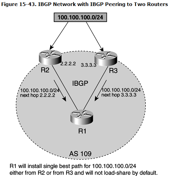
Figure 15-44 shows the flowchart to follow to resolve this problem.

Debugs and Verification
Example 15-83 shows output in R1 receiving two IBGP paths for prefix 100.100.100.0/24 but installing only one.
Example 15-83 Output of R1 Having Multiple IBGP Paths for 100.100.100.0/24 but Installing Only One in Its Routing Table
R1#show ip bgp 100.100.100.0
BGP routing table entry for 100.100.100.0/24, version 2
Paths: (2 available, best #1)
Not advertised to any peer
110
2.2.2.2(metric 11) from 2.2.2.2 (2.2.2.2)
Origin IGP, metric 0, localpref 100, valid, internal, best
110
3.3.3.3(metric 11) from 3.3.3.3 (3.3.3.3)
Origin IGP, metric 0, localpref 100, valid, internal
R1#show ip route 100.100.100.0
Routing entry for 100.100.100.0/24
Known via "bgp 109", distance 200, metric 0
Tag 110, type internal
Last update from 2.2.2.2 00:32:25 ago
Routing Descriptor Blocks:
2.2.2.2, from 2.2.2.2, 00:32:25 ago
Route metric is 0, traffic share count is 1
AS Hops 1
Solution
Cisco IOS Software allows, by configuration, the selection of multiple IBGP paths for the same prefix to go in the routing table, as demonstrated in Example 15-84.
Example 15-84 Configuration Addition in R1 to Allow Multiple IBGP Paths to Get Installed in the Routing Table for 100.100.100.0/24
R1# router bgp 109
neighbor 2.2.2.2 remote-as 109
neighbor 3.3.3.3 remote-as 109
neighbor 2.2.2.2 update-source loopback0
neighbor 3.3.3.3 update-source loopback0
maximum-paths ibgp 2
maximum-paths ibgp 2 allows two IBGP-learned paths to be installed in the routing table, and both paths are used in carrying traffic for 100.100.100.0/24. For maximum-paths ibgp to work, the following conditions must be met:
In both paths, all BGP attributes—LOCAL_PREF, MED,ORIGIN, and AS_PATH (entire AS_PATH)—must be identical.
Both paths must be learned through IBGP.
Both paths must be synchronized.
Both paths must have a reachable next hop.
Both paths must have an EQUAL IGP cost to the next hop.
Example 15-85 shows the output of BGP table in R1 after applying the maximum-paths ibgp command.
Example 15-85 Effect of Applying maximum-paths ibgp Command in R1
R1#show ip bgp 100.100.100.0
BGP routing table entry for 100.100.100.0/24, version 2
Paths: (2 available, best #2)
Not advertised to any peer
110
2.2.2.2 from 2.2.2.2 (2.2.2.2)
Origin IGP, metric 0, localpref 100, valid, internal, best, multipath
110
3.3.3.3 from 3.3.3.3 (3.3.3.3)
Origin IGP, metric 0, localpref 100, valid, internal, multipath
Both of these paths are marked as “multipath” in the highlighted BGP output, and both will be installed in the routing table, as shown in Example 15-86.
Example 15-86 Multiple IBGP Paths for 100.100.100.0/24 in the Routing Table of R1
R1# show ip route 100.100.100.0
Routing entry for 100.100.100.0/24
Known via "bgp 109", distance 200, metric 0
Tag 109, type internal
Last update from 88.88.88.78 00:34:36 ago
Routing Descriptor Blocks:
* 2.2.2.2, from 2.2.2.2, 00:34:36 ago
Route metric is 0, traffic share count is 1
AS Hops 1
3.3.3.3, from 3.3.3.3 00:34:36 ago
Route metric is 0, traffic share count is 1
AS Hops 1
Traffic from R1 sent to 100.100.100.0/24 will use both IBGP connections, thus load sharing across multiple IBGP connections.
Troubleshooting Inbound IP Traffic Flow Issues Because of BGP Policies
Just as in managing outbound IP traffic from an AS, Cisco IOS Software offers BGP operators configuration options to manage inbound traffic in an AS. It is important that inbound traffic from other autonomous systems be managed well. If this does not happen, capacity of the network will not be fully utilized. This causes congestion in one part of the network while the other parts are underutilized. The end result of this mismanagement of inbound traffic flow is sluggish throughput, slow round-trip times, and delays in IP traffic. Therefore, it is essential that all inbound BGP policies are checked and configured correctly.
Some of the most common problems in managing inbound IP traffic in an AS using BGP are as follows:
Multiple connections exist to an AS, but all the traffic comes in through one BGP neighbor, X, in the same AS.
A BGP neighbor in AS 110 should just be a backup provider, but some traffic from Internet still comes through AS 110.
Asymmetrical routing occurs.
Traffic to a certain subnet should come through a particular connection, but it is coming from somewhere else.
Problem: Multiple Connections Exist to an AS, but All the Traffic Comes in Through One BGP Neighbor, X, in the same AS—Cause: Either BGP Neighbor at X Has a BGP Policy Configured to Make Itself Preferred over the Other Peering Points, or the Networks Are Advertised to Attract Traffic from Only X
As Figure 15-45 illustrates, AS 109 has multiple BGP connections to AS 110, and AS 109 is advertising prefix 100.100.100.0/24 to AS 110 at all locations. However, all the traffic from AS 110 to 100.100.100.0/24 comes through the connection at X. All other links between the two autonomous systems are underutilized.

There might be multiple reasons for this behavior, but two of the most common scenarios are as follows:
AS 110 has the BGP policy configured so that all updates from AS 109 at location X get the LOCAL_PREFERENCE higher than at all other neighbors with AS 109. This results in making X the preferred exit point from AS 110 to AS 109 for 100.100.100.0/24.
In Figure 15-45, both R1 and R2 in AS 109 are advertising 100.100.100.0/24 to R6 and R8 in AS 110, respectively. R8 is changing the LOCAL_PREFERENCE of 100.100.100.0/24 so that R8 becomes the exit point from all BGP speakers in AS 110 to reach 100.100.100.0/24. This situation will make the link between R6 and R1 unutilized, and all the traffic to 100.100.100.0/24 will follow the R8–R2 link. The “Debugs and Verification” section explains how R8 can be configured to achieve this.
AS 109 is influencing traffic by advertising different MED values for the prefix 100.100.100.0/24 at different locations.
In Figure 15-46, both R1 and R2 are advertising 100.100.100.0/24, but with different MEDs. R1 is advertising a MED of 20, while a MED of 1 comes from R2 at X. In AS 110 BGP best-path selection, the lowest MED can influence this decision. As described in Chapter 14 in detail, if BGP best-path selection breaks the tie between the two paths based on the MED, the path from R2 will win and make it the most attractive exit point from AS 110 to AS 109 to reach 100.100.100.0/24. The “Debugs and Verification” section explains how R2 can be configured to achieve this.

Figure 15-47 shows the flowchart to follow to resolve this problem.

Debugs and Verification
This section discusses both cases of inbound traffic influence, discussed in the problem/cause presentation in the preceding section. Both necessary router configurations and show command outputs are displayed to examine the problem.
Case 1
This case is the one shown in Figure 15-45, in which R8 changed the LOCAL_PREFERENCE for 100.100.100.0/24. Example 15-87 shows the configuration in R8. The only significant con-figuration change is in R8, where route-map influencing_traffic is configured.
Example 15-87 R8 Configuration to Change LOCAL_PREFERENCE to Affect Best-Path Calculation of BGP
R8# router bgp 110
no synchronization
neighbor 172.16.28.2 remote-as 109
neighbor 172.16.28.2 route-map influencing_traffic in
neighbor 172.16.126.6 remote-as 110

!
access-list 1 permit 100.100.100.0
access-list 2 permit any
route-map influencing_traffic permit 10
match ip address 1
set local-preference 200
!
route-map influencing_traffic permit 20
match ip address 2
set local-preference 90
In Example 15-87, R8 is configured with route-map influencing_traffic sequence 10, which changes the LOCAL_PREFERENCE to 200 for prefix 100.100.100.0/24 permitted by access list 1. The highest LOCAL_PREFERENCE wins in BGP best-path calculation, which affects all IBGP speakers in AS 110 (R6, in this example) and makes the path from R8 the best exit point to reach 100.100.100.0/24. Sequence 20 of the route map influencing traffic changes the LOCAL_PREFERENCE attribute to 90 for all other routes learned from neighbor 172.16.28.2 (R2).
The output in Example 15-88 shows how BGP in R6 selects R8 as the best exit point. Notice that the first path (the best path) is an IBGP path from R6 to R8 with a LOCAL_PREFERENCE of 200. The second path is from the R1–R6 connection.
The output from R8 in Example 15-88 shows that it has only a path for 100.100.100.0/24 and that is from R2. LOCAL_PREFERENCE is shown as 200, making it a best path advertised to R6.
Example 15-88 show ip bgp Command Output Reveals the Best Exit Point
R6# show ip bgp 100.100.100.0
BGP routing table entry for 100.100.100.0/24, version 6
Paths: (2 available, best #1, table Default-IP-Routing-Table)
Advertised to non peer-group peers:
172.16.126.1
109
172.16.28.2 (metric 20) from 172.16.28.8 (172.16.8.8)
Origin IGP, metric 0, localpref 200, valid, internal, best
109
172.16.126.1 from 172.16.126.1 (172.16.1.1)
Origin IGP, metric 0, localpref 100, valid, external
_____________________________________________________________________________________
R8#show ip bgp 100.100.100.0
BGP routing table entry for 100.100.100.0/24, version 2
Paths: (1 available, best #1, table Default-IP-Routing-Table)
Not advertised to any peer
109
172.16.28.2 from 172.16.28.2 (172.16.2.2)
Origin IGP, metric 0, localpref 200, valid, external, best
Case 2
This case is the one shown in Figure 15-46, in which R1 and R2 advertise different MEDs for 100.100.100.0/24 to R6 and R8, respectively.
Example 15-89 details the configuration needed in R1 and R2. R6 and R8 have the standard BGP configuration for a simple neighbor relationship, so it is not shown. R1 and R2 have route-map MED_advertisement that advertises MEDs to their EBGP neighbors R6 and R8, respectively.
Example 15-89 MED Advertisement from R1 and R2 to Influence Inbound Traffic for 100.100.100.0/24
R1# router bgp 109
no synchronization
bgp log-neighbor-changes
network 100.100.100.0 mask 255.255.255.0
network 200.100.100.0
neighbor 172.16.126.2 remote-as 109
neighbor 172.16.126.6 remote-as 110
neighbor 172.16.126.6 route-map MED_advertisement out
access-list 1 permit 100.100.100.0
access-list 2 permit any
!
route-map MED_advertisement permit 10
match ip address 1
set metric 20
!
route-map MED_advertisement permit 20
match ip address 2
set metric 100
_____________________________________________________________________________________
R2# router bgp 109
no synchronization
network 100.100.100.0 mask 255.255.255.0
neighbor 172.16.28.8 remote-as 110
neighbor 172.16.28.8 route-map MED_advertisement out
neighbor 172.16.126.1 remote-as 109
!
!
access-list 1 permit 100.100.100.0
access-list 2 permit any
route-map MED_advertisement permit 10
match ip address 1
set metric 1
!
route-map MED_advertisement permit 20
match ip address 2
set metric 200
In Example 15-89, R1 and R2 have route-map MED_advertisement configured with neighbors R6 and R8, respectively. In the case of R1, sequence 10 of the route map sets MED of 20 for 100.100.100.0/24 by access list 1 and sets the rest of the prefix MED to 100 by sequence 20 of the route map.
R2 is configured in a similar manner to R1, but the MED of 1 is sent to R8 for 100.100.100.0/24 and a MED of 200 is sent for rest of the prefixes.
The output in Example 15-90 shows the BGP output of prefix 100.100.100.0/24. The MED value of 1 is learned from R2 at R8, making this route the best route in AS 110.
All traffic from AS 110 to prefix 100.100.100.0/24 will exit from X at R8. Notice the output in R6, which prefers the IBGP update from R8 because of a lower MED for prefix 100.100.100.0/24.
Example 15-90 BGP Output for Prefix 100.100.100.0/24 Reveals the Best Route
R8#show ip bgp 100.100.100.0
BGP routing table entry for 100.100.100.0/24, version 12
Paths: (1 available, best #1, table Default-IP-Routing-Table)
Advertised to non peer-group peers:
172.16.126.6
109
172.16.28.2 from 172.16.28.2 (172.16.2.2)
Origin IGP, metric 1, localpref 100, valid, external, best
_____________________________________________________________________________________
R6#show ip bgp 100.100.100.0
BGP routing table entry for 100.100.100.0/24, version 13
Paths: (2 available, best #2, table Default-IP-Routing-Table)
Advertised to non peer-group peers:
172.16.126.1
109
172.16.126.1 from 172.16.126.1 (172.16.1.1)
Origin IGP, metric 20, localpref 100, valid, external
109
172.16.28.2 (metric 20) from 172.16.28.8 (172.16.8.8)
Origin IGP, metric 1, localpref 100, valid, internal, best
Solution
Return traffic influence can be desired as in Case 2, or it might happen as in Case 1. AS 109 BGP operators must understand what is causing this influence.
In Case 1, in which AS 110 changed its BGP policy by altering the LOCAL_PREFERENCE, BGP does not offer any commands for AS 109 to influence the AS 110 policy. Each AS can force its own policy, and the outside AS cannot change that. The solution for the Case 1 problem lies with the AS 109 administrator requesting AS 110 to remove any policy that affects AS 109.
In Case 2, AS 109 announced a MED and AS 110 was not configured to change LOCAL_PREFERENCE (as in Case 1).
If the MED announcement is not producing the desired behavior for AS 109 inbound traffic management, these MEDs should be removed, and the normal BGP policies of AS 110 should decide on the best entry into AS 109.
In larger BGP networks with numerous exit points and multiple BGP AS connections, traffic balance could become a challenge. Therefore, careful BGP policies and peering agreements must be created between BGP speakers, and traffic flow must be carefully observed.
Problem: Multiple Connections Exist to Several BGP Neighbors, but Most of the Traffic from Internet to 100.100.100.0/24 Always Comes in Through One BGP Neighbor from AS 110—Cause: Route Advertisements for 100.100.100.0/24 in AS 109 Attract Internet Traffic Through That BGP Neighbor in AS 110
When a BGP prefix is observed from a global Internet point-of-view, few BGP attributes stay intact from the originator of that prefix. For example, AS_PATH, ORIGIN_CODE and AGGREGATOR are the most common BGP attributes that get carried no matter how many autonomous systems a BGP update crosses. The most popular attributes, LOCAL_PREFERENCE and MED, do not cross an AS boundary. Therefore, they do not play any role in influencing return traffic from sources multiple autonomous systems away.
As discussed in Chapter 14, the most common BGP attributes that get used in the BGP best-path algorithm are LOCAL_PREFERENCE, AS_PATH and MED. Out of these, AS_PATH is the only attribute that stays intact from the originator of the prefix to any Internet BGP speaker.
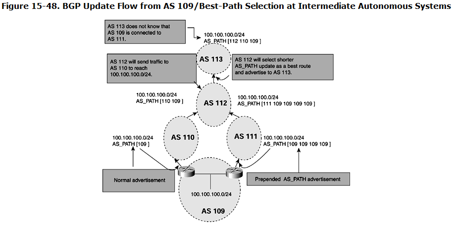
Figure 15-48 shows the BGP update flow from AS 109 and also shows BGP best-path selection at each intermediate AS. AS 109 is originating AS 100.100.100.0/24, and its goal is to receive traffic from the Internet for 100.100.100.0/24 only through AS 110, not through AS 111.
Solution
The following are two common practices that BGP administrators use to achieve the previously mentioned goal:
- AS 109 advertises network 100.100.100.0/24 with a much longer AS_PATH list to all BGP neighbors except AS 110. If autonomous systems 110, 112, and 113 do not make any additional changes in the BGP policy, autonomous systems 112 and 113 always go through AS 110 to reach 100.100.100.0/24.
- This results in all traffic to network 100.100.100.0/24 entering AS 109 to traverse AS 110; the links between AS 109 and AS 111 for redundancy.
- AS 109 advertises 100.100.100.0/24 only to AS 110, not to BGP neighbor AS 111. Therefore, traffic from the Internet sees only one path to reach 100.100.100.0/24—through AS 110 to AS 109. However, this case loses redundancy if AS 109 loses its BGP session with AS 110.