Securing Layer 2 Devices
Defending Against Layer 2 Attacks
This section begins by exploring the nature of Layer 2 switch operation and why it is such an attractive target for attackers. Then, approaches for mitigating a variety of Layer 2 attacks are addressed. These strategies include best practices for securing a Layer 2 network, protecting against VLAN hopping attacks, preventing an attacker from manipulating Spanning Tree Protocol (STP) settings, stopping DHCP server and ARP spoofing, preventing Content Addressable Memory (CAM) table overflow attacks, and disallowing MAC address spoofing. Other switch-related security topics include port security, Switch Port Analyzer (SPAN), Remote SPAN (RSPAN), VLAN access control lists (VACL), private VLANs, rate limiting, and MAC address notification.
Review of Layer 2 Switch Operation
Shared media hubs have largely been eliminated from today’s corporate networks, with Ethernet switches taking their place. An Ethernet switch learns the MAC addresses connected off each of its ports. Then, when a frame enters the switch, the switch forwards the frame based on the frame’s destination MAC address. However, if the switch does not have the frame’s destination MAC address stored in its CAM table (also known as a MAC address table), or if the frame’s destination MAC address is a broadcast address of all Fs (that is, FFFF.FFFF.FFFF), the frame is forwarded out all ports other than the port it was received on.
Many Ethernet switches can also logically group ports to form a Virtual LAN (VLAN), where each VLAN is its own broadcast domain. Traffic must be routed to travel from one
VLAN to another VLAN.
Cisco Catalyst switches operate at Layer 2 of the OSI model (the Data Link Layer), as illustrated in Figure 6-1. If an attacker were to gain control of an Ethernet switch operating at Layer 2, all the upper layers could be compromised. As a result, Layer 2 switches, such as a series of Cisco Catalyst switches, might appear to be an attractive target of attacks.

Basic Approaches to Protecting Layer 2 Switches
Although this chapter explores several advanced approaches to securing Ethernet switches, for now, consider the following basic approaches to Layer 2 protection, which should be applied to switches throughout the network:
- Telnet access: Administrators can connect to a Cisco Catalyst switch using Telnet. Unfortunately, Telnet is not a secure protocol. If an attacker intercepted the Telnet packets, he might be able to glean the password credentials necessary to gain administrative access to the switch. Therefore, Secure Shell (SSH) is preferred as an alternative to Telnet, because it offers confidentiality and data integrity. Administrators alternatively can configure the switch via a switch’s console port. Therefore, this console port should have physical security (for example, it should be locked away from physical access by a user).
- SNMP access: Simple Network Management Protocol (SNMP) is often used by a network management station to collect information about network devices. Older versions of SNMP (for example, version 1 and version 2c) lack strong security mechanisms. If these older versions are used, consider allowing SNMP to only read information, rather than read and write information. Alternatively, you might consider using SNMP version 3, which does implement strong security mechanisms.
- Reducing exposure: Just as server administrators can reduce their server’s exposure to attacks by turning off unneeded services, switch administrators can reduce a switch’s exposure to attacks by disabling any unneeded services and any unused Ethernet ports. Additionally, administrators can limit the number of MAC addresses that ports can learn.
- Logging: As with routers, logging attempts to access the switch. Regularly reviewing those logs can alert switch administrators to potential threats.
- Change control: In enterprise networks, multiple switch administrators might share the responsibility for switch configuration. Therefore, consider a formalized change control policy to better coordinate administrative activity.
- VLAN configuration: Consider the following recommendations when configuring switch VLANs:
- Configure ports that do not need to form a trunk to a trunk setting of “off,” as opposed to “auto.”
- Do not send user data over an IEEE 802.1Q trunk’s native VLAN.
- Use private VLANs to prevent an attacker from compromising one host in a VLAN and then using that host as a jumping-off point to attack other hosts within the VLAN.
Preventing VLAN Hopping
A VLAN hopping attack allows traffic from one VLAN to pass into another VLAN, without first being routed. An attacker could use a VLAN hopping attack to, for example, eavesdrop on traffic that the attacker’s PC is supposed to be isolated from or to send traffic to a VLAN that the attacker’s PC should not be able to reach. The two main approaches for launching a VLAN hopping attack are switch spoofing and double tagging.
Switch Spoofing
By default, Ethernet trunks on Cisco Catalyst switches carry traffic for all VLANs. Therefore, if an attacker can persuade a switch to go into trunking mode, the attacker could then see traffic for all VLANs. In some cases this type of attack could be used to discover username and password credentials that the attacker could use for a later attack. Some Cisco Catalyst switch ports default to auto mode for trunking, which means that the ports automatically become trunk ports if they receive Dynamic Trunking Protocol (DTP) frames. An attacker could attempt to make his switch port enter trunking mode either by spoofing DTP frames or by connecting a rogue switch to his switch port. To combat switch spoofing, you can disable trunking on all ports that do not need to form trunks, and disable DTP on ports that do need to be trunks.
Example 6-1 illustrates how to disable trunking on a Cisco Catalyst 3550 switch port, and Example 6-2 demonstrates how to configure a port to act as a trunk port, without the use of DTP.
Example 6-1 Disabling Trunking
Cat3550(config)# interface gigabitethernet 0/3
Cat3550(config-if)# switchport mode access
Cat3550(config-if)# exit
Example 6-2 Preventing the Use of DTP
Cat3550(config)# interface gigabitethernet 0/4
Cat3550(config-if)# switchport trunk encapsulation dot1 q
Cat3550(config-if)# switchport mode trunk
Cat3550(config-if)# switchport nonegotiate
Double Tagging
On an IEEE 802.1Q trunk, one VLAN is designated as the native VLAN. The native VLAN does not add any tagging to frames traveling from one switch to another switch. If an attacker’s PC belonged to the native VLAN, the attacker could leverage this native VLAN characteristic to send traffic that has two 802.1Q tags. Specifically, the traffic’s outer tag is for the native VLAN, and the traffic’s inner tag (which is not examined by the switch’s ingress port) is for the target VLAN to which the attacker wants to send traffic.
As illustrated in Figure 6-2, the first switch (SW1) removes the outer tag from the frame before forwarding the frame to its neighboring switch (SW2), because the outer tag specifies the native VLAN (VLAN 1 in this example), which is not tagged by a switch. As a result, when the frame is transmitted from switch SW1 to SW2, the inner tag becomes visible to SW2. This inner tag specifies the target VLAN (VLAN 100 in this example). As a result, SW2 sends the traffic out to the target VLAN.
To help prevent a VLAN hopping attack using double tagging, do not use the native VLAN to send user traffic. You can accomplish this by creating a VLAN in your organization that does not have any ports. This unused VLAN is solely for the purpose of native VLAN assignment. Example 6-3 shows a configuration on a Cisco Catalyst 3550 in which the native VLAN has been set to an unused VLAN.
 Example 6-3 Setting the Native VLAN
Cat3550(config)# interface gigabitethernet 0/4
Cat3550(config-if)# switchport trunk native vlan 400
Protecting Against an STP Attack
Redundant links can be introduced into a Layer 2 switch topology to increase the network’s availability. However, redundant links can potentially cause Layer 2 loops, which can result in broadcast storms. Fortunately, Spanning Tree Protocol (STP) can allow you to physically have redundant links while logically having a loop-free topology, thus preventing the potential for broadcast storms.
STP achieves this loop-free topology by electing one switch as the root bridge. The network administrator can influence which switch becomes the root bridge by manipulating a switch’s bridge priority, in which the switch with the lowest bridge priority becomes the root bridge. Every other switch in the network designates a root port, which is the port on the switch that is “closest” to the root bridge, in terms of “cost.” The bridge priorities of switches are learned through the exchange of Bridge Protocol Data Units (BPDU). After the election of a root bridge, all the switch ports in the topology are either in the blocking state (where user data is not forwarded) or in the forwarding state (where user data is forwarded).
If the root bridge fails, the STP topology reconverges by electing a new root bridge. Note that a port does not immediately transition from the blocking state to the forwarding state. Rather, a port transitions from blocking, to listening, to learning, to forwarding.
If an attacker has access to two switch ports (each from a different switch), he can introduce a rogue switch into the network. The rogue switch can then be configured with a lower bridge priority than the bridge priority of the root bridge. After the rogue switch announces its “superior BPDUs,” the STP topology reconverges. All traffic traveling from one switch to another switch now passes through the rogue switch, thus allowing the attacker to capture that traffic.
For example, consider the topology shown in Figure 6-3. Data traveling from PC1 to Server1 passes through SW2 and SW3 (the root bridge).

Notice PC2 and PC3. If an attacker gained access to the switch ports of these two PCs, he could introduce a rogue switch that advertised superior BPDUs, causing the rogue switch to be elected as the new root bridge. The new data path between PC1 and Server1, as shown in Figure 6-4, now passes through the attacker’s rogue switch. The attacker can configure one of the switch ports as a Switch Port Analyzer (SPAN) port. A SPAN port can receive a copy of traffic crossing another port or VLAN. In this example, the attacker could use the SPAN port to receive a copy of traffic crossing the switch destined for the attacker’s PC.

Consider two approaches for protecting a network from this type of STP attack:
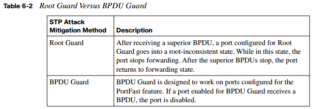
- Protecting with Root Guard: The Root Guard feature can be enabled on all switch ports in the network off of which the root bridge should not appear (that is, every port that is not a root port, the port on each switch that is considered to be closest to the root bridge). If a port configured for Root Guard receives a superior BPDU, instead of believing the BPDU, the port goes into a root-inconsistent state. While a port is in the root-inconsistent state, no user data is sent across it. However, after the superior BPDUs stop, the port returns to the forwarding state. Example 6-4 illustrates the configuration of Root Guard on a port.
Example 6-4 Configuring Root Guard
Cat3550(config)# interface gigabitethernet 0/1
Cat3550(config-if)# spanning- tree guard root
- Protecting with BPDU Guard: The BPDU Guard feature is enabled on ports configured with the Cisco PortFast feature. The PortFast feature is enabled on ports that connect to end-user devices, such as PCs. It reduces the amount of time required for the port to go into forwarding state after being connected. The logic of PortFast is that a port that connects to an end-user device does not have the potential to create a topology loop. Therefore, the port can go active sooner by skipping STP’s listening and
learning states, which by default take 15 seconds each. Because these PortFast ports are connected to end-user devices, they should never receive a BPDU. Therefore, if a port enabled for BPDU Guard receives a BPDU, the port is disabled. Example 6-5 shows a sample BPDU Guard configuration.
Example 6-5 Configuring BPDU Guard
Cat3550(config)# interface gigabitethernet 0/2
Cat3550(config-if)# spanning- tree portfast bpduguard
Combating DHCP Server Spoofing
On today’s networks, most clients obtain their IP address information dynamically, using Dynamic Host Configuration Protocol (DHCP), rather than having their IP address information statically configured. To dynamically obtain IP address information, a client (for example, a PC) sends out a DHCP request. A DHCP server sees the request, and a DHCP response (including such information as an IP address, subnet mask, and default gateway) is sent to the requesting client.
However, if an attacker connects a rogue DHCP server to the network, the rogue DHCP server can respond to a client’s DHCP request. Even though both the rogue DHCP server and the actual DHCP server respond to the request, the client uses the rogue DHCP server’s response if it reaches the client before the response from the actual DHCP server. This is shown in Figure 6-5.

The DHCP response from an attacker’s DHCP server might assign the attacker’s IP address as the client’s default gateway or DNS server. As a result, the client could be influenced to send traffic to the attacker’s IP address. The attacker can then capture the traffic and forward the traffic to an appropriate default gateway. Because, from the client’s perspective, everything is functioning correctly, this type of DHCP server spoofing attack can go undetected for a long period of time.
The DHCP snooping feature on Cisco Catalyst switches can be used to combat a DHCP server spoofing attack. With this solution, Cisco Catalyst switch ports are configured in either the trusted or untrusted state. If a port is trusted, it is allowed to receive DHCP responses (for example, DHCPOFFER, DHCPACK, or DHCPNAK). Conversely, if a port is untrusted, it is not allowed to receive DHCP responses, and if a DHCP response attempts to enter an untrusted port, the port is disabled.
Fortunately, not every switch port needs to be configured to support DHCP snooping. If a port is not explicitly configured as a trusted port, it is implicitly considered to be an untrusted port. To configure DHCP snooping, the feature must first be enabled. Use the following command to globally enable DHCP snooping:
Cat3550(config)# ip dhcp snooping
You can also enable DHCP snooping for specific VLANs. For example, to enable DHCP snooping for VLANS 1 and 100, in addition to VLANs in the range of 200 to 210, use the following global configuration mode command:
Cat3550(config)# ip dhcp snooping vlan 1 , 1 00, 200- 21 0
After you enable the DHCP snooping feature, specific switch interfaces can be configured as trusted ports, as the following syntax demonstrates:
Cat3550(config)# interface gigabitethernet 0/4
 Cat3550(config-if)# ip dhcp snooping trust
Another type of DHCP attack is more of a DoS attack against the DHCP server. Specifically, the attacker can repeatedly request IP address assignments from the DHCP server, thus depleting the pool of addresses available from the DHCP server. The attacker can accomplish this by making the DHCP requests appear to come from different MAC addresses. To mitigate such a denial-of-service (DoS) attack, the previously mentioned DHCP snooping feature can be used to limit the number of DHCP messages per second that are allowed on an interface, thus preventing a flood of spoofed DHCP requests. For example, to limit the number of DHCP messages on a port to three messages per second, use the following syntax:
Cat3550(config)# interface gigabitethernet 0/5
Cat3550(config-if)# ip dhcp snooping limit rate 3
Using Dynamic ARP Inspection
The DHCP snooping feature dynamically builds a DHCP binding table, which contains the MAC addresses associated with specific IP addresses. Additionally, this feature supports static MAC address to IP address mappings, which might be appropriate for network devices, such as routers. This DHCP binding table can be used by the Dynamic ARP Inspection (DAI) feature to help prevent Address Resolution Protocol (ARP) spoofing attacks.
Recall the purpose of ARP requests. When a network device needs to determine the MAC address that corresponds to an IP address, the device can send an ARP request. The target device replies to the requesting device with an ARP reply. The ARP reply contains the requested MAC address.
Attackers can attempt to launch an attack by sending gratuitous ARP (GARP) replies. These GARP messages can tell network devices that the attacker’s MAC address corresponds to specific IP addresses. For example, the attacker might be able to convince a PC that the attacker’s MAC address is the MAC address of the PC’s default gateway. As a result, the PC starts sending traffic to the attacker. The attacker captures the traffic and then forwards the traffic to the appropriate default gateway.
To illustrate, consider Figure 6-6. PC1 is configured with a default gateway of 192.168.0.1. However, the attacker sends GARP messages to PC1, telling PC1 that the MAC address corresponding to 192.167.0.1 is BBBB.BBBB.BBBB, which is the attacker’s MAC address. Similarly, the attacker sends GARP messages to the default gateway, claiming that
the MAC address corresponding to PC1’s IP address of 192.168.0.2 is BBBB.BBBB.BBBB. This ARP cache poisoning causes PC1 and Router1 to exchange traffic via the attacker’s PC. Therefore, this type of ARP spoofing attack is considered to be a man-in-the-middle attack.

Networks can be protected from ARP spoofing attacks using the DAI feature. DAI works similarly to DHCP snooping by using trusted and untrusted ports. ARP replies are allowed into the switch on trusted ports. However, if an ARP reply enters the switch on an untrusted port, the contents of the ARP reply are compared to the DHCP binding table to verify its accuracy. If the ARP reply is inconsistent with the DHCP binding table, the ARP reply is dropped, and the port is disabled.
The first step in configuring DAI is to enable DAI for one or more VLANs. For example, to enable DAI for VLAN 100, enter the following global configuration mode command:
Cat3550(config)# ip arp inspection vlan 1 00
By default, the DAI feature considers all switch ports to be untrusted ports. Therefore, trusted ports must be explicitly configured. These trusted ports are the ports on which ARP replies are expected. For example, to configure port Gigabit 0/6 to be a DAI trusted port, use the following syntax:
Cat3550(config)# interface gigabitethernet 0/6
Cat3550(config-if)# ip arp inspection trust
Mitigating CAM Table Overflow Attacks
A Cisco Catalyst switch uses a Content Addressable Memory (CAM) table to store the information used by the switch to make forwarding decisions. Specifically, the CAM table contains a listing of MAC addresses that have been learned from each switch port. Then, when a frame enters the switch, the switch interrogates the frame’s destination MAC address. If the destination MAC address is known to exist off one of the switch ports, the
frame is forwarded out only that port. For example, consider Figure 6-7. PC1 sends packets to PC2 via switch SW1. Because the switch knows the MAC addresses of PC1 and PC2 in its CAM table, the traffic flows only between interface Gig 0/1 and Gig 0/2.

The switch’s CAM table, however, does have a finite size. Therefore, if the CAM table ever fills to capacity, the switch is unable to learn new MAC addresses. As a result, when frames arrive destined for these unlearned MAC addresses, the switch floods a copy of these frames out all other switch interfaces, other than the interfaces they were received on.
The attacker’s PC is connected to interface Gig 0/3, and the attacker wants to receive a copy of the traffic flowing between PC1 and PC2. If the attacker had caused the switch’s CAM table to overflow before the switch learned the MAC addresses of PC1 and PC2, traffic between these two PCs would be flooded out all other switch ports, other than the ports the traffic was received on, allowing the attacker’s PC to see and capture the traffic, as shown in Figure 6-8. This behavior of flooding frames with an unlearned destination MAC address is called fail-open mode.
Figure 6-8 Flooding Behavior After a CAM Table Overflow Attack

An attacker could launch a CAM table overflow attack using a utility such as macof, which is a component of a suite of utilities called dsniff. The macof utility can generate as many as 155,000 MAC addresses in a minute. After a short time, the switch learns so many MAC addresses from the attacker’s PC that the switch’s CAM table overflows, thus forcing the flooding of frames with unlearned MAC addresses. This type of attack noticeably impacts network performance, potentially causing applications to drop packets or even crash. As a result, a CAM table overflow attack is by no means a stealth attack, which an attacker might expect to launch without detection.
Keep in mind that the CAM table size can vary by switch model. Fortunately, Cisco Catalyst switches support a port security command, discussed later in this chapter. It allows the switch administrator to specify the maximum number of MAC addresses that can be learned on a port, thus preventing a CAM table overflow attack.
Spoofing MAC Addresses
Another type of attack targeted at the switch’s CAM table is a MAC address spoofing attack. An attacker sends a frame with a false source MAC address—specifically, the MAC address of another device on the network. Under normal conditions, as shown in Figure 6-9, the switch’s CAM table contains the correct MAC address of the stations attached to the switch’s ports.

However, Figure 6-10 shows the attacker’s PC sending a frame to the switch. It incorrectly shows a source MAC address of DDDD.DDDD.DDDD, which is actually the MAC address of PC2. This frame causes the switch to update its CAM table to show that DDDD.DDDD.DDDD is available off port Gig 0/3, which allows the attacker’s PC to start capturing traffic destined for PC2.

This condition of the attacker’s PC receiving traffic for PC2, as shown in Figure 6-11, is a temporary condition. When PC2 sends another source frame into the switch, the switch relearns PC2’s MAC address of DDDD.DDDD.DDDD on port Gig 0/2. However, even though the problem corrects itself, in the interim, the attack disrupts the normal traffic flow and allows the attacker to receive traffic intended for another device (that is, PC2 in this example).

To mitigate MAC address spoofing attacks, a switch administrator can configure the Cisco Catalyst switch to use sticky secure MAC addresses. When configured for sticky secure MAC addresses, a Catalyst switch dynamically learns MAC addresses connected to various ports. These dynamically learned MAC addresses are added to the switch’s running configuration, thus preventing an attacker from spoofing a previously learned address. Port security configuration is covered in great detail later in this chapter.
Additional Cisco Catalyst Switch Security Features
No single network device secures an entire network from all potential attacks. Rather, multiple hardware and/or software solutions work in tandem to help secure the overall network. For example, virtual private networks (VPN) and firewalls can help protect sensitive traffic from eavesdroppers and prevent unwanted traffic from entering a network. As described earlier in this chapter, a Layer 2 Cisco Catalyst switch can also aid in network security. The additional Cisco Catalyst switch security features described in the following sections can further secure a network infrastructure.
Using the SPAN Feature with IDS
Chapter 11, “Using Cisco IOS IPS to Secure the Network,” discusses the Cisco Intrusion Detection System (IDS) technology. With IDS, a sensor receives a copy of traffic for analysis. If the sensor recognizes the traffic as being malicious or suspicious, the IDS sensor can take a preconfigured action, such as generating an alarm or dynamically configuring a firewall to block the sender.
One way to cause an IDS sensor to receive a copy of network traffic is to configure a port on a Cisco Catalyst switch for the Switched Port Analyzer (SPAN) feature. SPAN allows a copy of traffic destined for another port to be sent out the SPAN port, thus allowing an attached IDS sensor to receive a copy of the traffic, as illustrated in Figure 6-12. Example 6-6 demonstrates how to configure port Gig 0/2 as a SPAN source and port Gig 0/3 as a SPAN destination port.

Example 6-6 Configuring a SPAN Port
Cat3550(config)# monitor session 1 source interface gigabitethernet0/2
Cat3550(config)# monitor session 1 destination interface gigabitethernet0/3
Cat3550(config)# end
Example 6-6 shows the SPAN port residing on the same switch as the destination port.
However, Cisco Catalyst switches also support the Remote SPAN (RSPAN) feature, which allows a SPAN port to be configured on a different switch.
Enforcing Security Policies with VACLs
Routers can use IP access control lists (ACL) to permit or deny specific traffic from entering or exiting a network interface. Therefore, ACLs are used as traffic travels between network address spaces.
However, a Cisco Catalyst switch can have an ACL applied within a VLAN. This intraVLAN ACL is called a VLAN access control list (VACL). Example 6-7 shows the configuration of a VACL that permits Telnet traffic to be sent to a host at IP address 10.1.1.2 while denying all other traffic. Notice that a vlan access-map named ALLOWTELNET is configured to match access list 100. For sequence number 10, the specified action is to forward traffic matching that access list. All other traffic is dropped because of a default implicit drop instruction, which drops all traffic not explicitly permitted. Finally, the VLAN filter (that is, the VACL) is applied to VLANs in the range 1 to 100.
Example 6-7 Configuring a VACL
Cat3550(config)# access- list 1 00 permit tcp any host 1 0. 1 . 1 . 2 eq telnet
Cat3550(config)# vlan access- map ALLOWTELNET 1 0
Cat3550(config-access-map)# match ip address 1 00
Cat3550(config-access-map)# action forward
Cat3550(config-access-map)# exit
Cat3550(config)# vlan filter ALLOWTELNET vlan- list 1 - 1 00
Isolating Traffic Within a VLAN Using Private VLANs
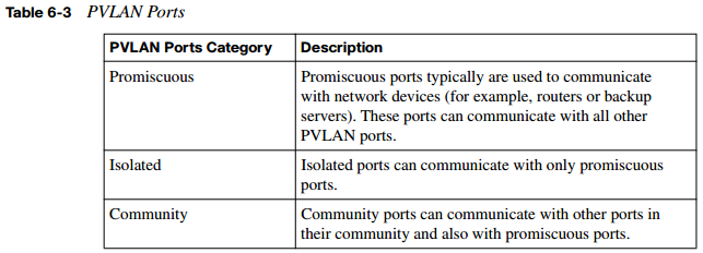
Another way for a Cisco Catalyst switch to provide security is through the use of private VLANs (PVLAN). These PVLANs can provide privacy between groups of Layer 2 ports on a Cisco Catalyst switch. A PVLAN domain has a single primary VLAN. Additionally, the PVLAN domain contains secondary VLANs that provide isolation between ports in a PVLAN domain. Cisco Catalyst switches support two categories of secondary VLANs:
- Isolated VLANs: Ports belonging to an isolated VLAN lack Layer 2 connectivity between one another.
- Community VLANs: Ports belonging to a community VLAN can communicate with one another, but not with ports in other community VLANs. PVLAN ports fall into one of three categories, as described in Table 6-3.
To learn more about private VLANs and their configuration, consult Building Cisco Multilayer Switched Networks (BCMSN) Authorized Self-Study Guide, Fourth Edition, available from Cisco Press.
Traffic Policing
To prevent an attacker from flooding a network with traffic in a DoS attack, Cisco Catalyst switches can rate-limit traffic using a traffic policing mechanism. Specifically, a traffic policing configuration allows an administrator to configure a committed information rate (CIR), which can be thought of as a “speed limit” on specific traffic. If traffic conforms to the speed limit, typically it is transmitted. However, traffic policing can alternatively transmit the conforming traffic and set a quality of service (QoS) marking (for example, a Differentiated Services Code Point [DSCP] marking) for the traffic. If traffic exceeds the speed limit, it can be dropped, or the switch can attempt to transmit the traffic while optionally setting the traffic’s priority value to a lower priority value.
The configuration of traffic policing is performed using the three-step Modular QoS CLI (MQC) approach. For more information on the MQC approach, consult Cisco Catalyst QoS: Quality of Service in Campus Networks, available from Cisco Press. Notifying Network Managers of CAM Table Updates Cisco Catalyst switches can proactively notify network administrators when CAM table updates occur. For example, if a switch learns a new MAC address and adds it to the CAM table, the Cisco Catalyst switch could send a Simple Network Management Protocol (SNMP) trap (that is, a notification) to a network management station (NMS). Similarly, a trap could be sent when a MAC address is deleted from the CAM table. The mac addresstable notification command is used to enable this notification feature.
Port Security Configuration
Earlier in this chapter you saw that Cisco Catalyst port security features can be used to combat CAM table overflow attacks and MAC address spoofing attacks. Cisco recommends that port security be configured on a switch before a switch is deployed in the network, to be proactive instead of reactive. When a switch port security violation occurs, you can configure the switch port to respond in one of three ways:
- Protect: When configured for protect, a switch port drops frames with an unknown source MAC address after the switch port reaches its configured maximum number of secure MAC addresses. However, frames with known (that is, learned) source MAC addresses are transmitted. Also, no notifications are sent if a port security violation occurs.
- Restrict: The restrict option operates similarly to the protect option. However, the restrict option sends an SNMP trap and a syslog message and increments a violation counter when a port security violation occurs.
- Shutdown: The shutdown option is the strictest approach. Not only does the shutdown option generate the same notifications as the restrict option, but it also shuts down the port. Therefore, after a port security violation occurs, no traffic is transmitted on that port.
A port security violation doesn’t occur only after a port learns a maximum number of MAC addresses or after an unknown source MAC address attempts to enter the port. A violation also can occur when a MAC address on one secure port appears on a different secure port. Ports support one of three types of secure MAC addresses:
- Static secure MAC address: An administrator can statically configure which MAC addresses exist off specific ports using the switchport port-security mac-address address command issued in interface configuration mode. These statically configured MAC addresses are added to a switch’s running configuration and CAM table.
- Sticky secure MAC address: Similar to static secure MAC addresses, ports configured for sticky secure MAC addresses also store MAC address-to-port associations in their switch’s running configuration and CAM table. However, the MAC addresses do not need to be statically configured. Rather, a switch port dynamically learns the MAC addresses that exist off its ports.
- Dynamic secure MAC address: Similar to sticky secure MAC addresses, ports configured for dynamic secure MAC addresses dynamically learn which MAC addresses exist off specific ports. However, dynamic secure MAC addresses are stored only in a switch’s CAM table, not in a switch’s running configuration.
By default, port security is not enabled on a Cisco Catalyst switch port. After enabling port security with the switchport port-security interface configuration mode command, the maximum number of secure MAC addresses on a port defaults to one, and the violation mode defaults to shutdown.
Example 6-8 offers a comprehensive example of configuring port security on a Cisco Catalyst switch. Commands might vary somewhat based on the switch platform. This example is configured on a Cisco Catalyst 3550 switch.
Example 6-8 Comprehensive Port Security Configuration
Cat3550(config)# interface gigabitethernet 0/5
Cat3550(config-if)# switchport mode access
Cat3550(config-if)# switchport port- security
Cat3550(config-if)# switchport port- security maximum 5
Cat3550(config-if)# switchport port- security violation protect
Cat3550(config-if)# switchport port- security mac- address 1 234. 1 234. 1 234
Cat3550(config-if)# switchport port- security mac- address sticky
Cat3550(config-if)# end
Notice that the administrator enters interface configuration mode for interface Gigabit Ethernet 0/5. In interface configuration mode, the administrator prevents the port from forming a trunk by issuing the switchport mode access command. Next, port security is enabled using the switchport port-security command. Recall that with port security enabled for a port, only one MAC address can be learned on that port. That number is increased to five in this example with the switchport port-security maximum 5 command. The default action to take in the event of a security violation is to shut down the port. The switchport port-security violation protect command is used to override the default behavior of shutting down.
It also allows the learned (or configured) MAC addresses to be transmitted while not allowing unknown (that is, not learned or configured) MAC addresses to be transmitted. Also, notice that the switchport port-security mac-address 1234.1234.1234 command trains the switch about a MAC address available off interface Gigabit Ethernet 0/5. Finally, the switchport port-security mac-address sticky command causes learned MAC addresses to be dynamically entered into the switch’s running configuration, thus mitigating a MAC address spoofing attack. Multiple show commands can be used to verify and troubleshoot an interface’s port security configuration. Example 6-9 shows the output from the show port-security command.
Example 6-9 Output from the show port-security Command
Cat3550# show port- security
 Secure Port MaxSecureAddr CurrentAddr SecurityViolation Security Action
 (Count) (Count) (Count)
 ---------------------------------------------------------------------------
 Gi0/5 5 1 0 Protect
 ---------------------------------------------------------------------------
 Total Addresses in System (excluding one mac per port) : 0
 Max Addresses limit in System (excluding one mac per port) : 6176

Example 6-10 shows output from the show port-security address command.
 Example 6-10 Output from the show port-security address Command
 Cat3550# show port- security address
 Secure Mac Address Table
 ------------------------------------------------------------------------
 Vlan Mac Address Type Ports Remaining Age
 (mins)
 ---- ----------- ---- ----- -------------
 1 1234.1234.1234 SecureConfigured Gi0/5 -
 ------------------------------------------------------------------------
 Total Addresses in System (excluding one mac per port) : 0
 Max Addresses limit in System (excluding one mac per port) : 6176
As an additional illustration, Example 6-11 shows how the show port-security interface interface-id command can be used to view detailed port security configuration information for an interface.
Example 6-11 Output from the show port-security interface Command
Cat3550# show port- security interface gigabitethernet 0/5
Port Security : Enabled
Port Status : Secure-down
Violation Mode : Protect
Aging Time : 0 mins
Aging Type : Absolute
SecureStatic Address Aging : Disabled
Maximum MAC Addresses : 5
Total MAC Addresses : 1
Configured MAC Addresses : 1
Sticky MAC Addresses : 0
Last Source Address:Vlan : 0000.
Configuration Recommendations
Based on the Layer 2 attack mitigation strategies discussed earlier, the following list summarizes the recommended Cisco procedures for securing Layer 2 networks:
- Limit management access for a Layer 2 switch to trusted administrators.
- If management protocols are used on a switch, use secure management protocols (such as SNMPv3) as opposed to management protocols that transmit information in plain text (such as SNMPv1 and SNMPv2c).
- Disable any services running on the switch that are not necessary.
- Use a port security configuration to limit the number of allowable MAC addresses that a port can learn.
- Do not send user data over a native VLAN on an IEEE 802.1Q trunk.
- Administratively shut down any unused ports.
- Use STP protection mechanisms such as Root Guard and BPDU Guard.
- Enable DHCP snooping and DAI to combat man-in-the-middle attacks.
Cisco Identity-Based Networking Services
Cisco Catalyst switches can also participate in a Cisco Identity-Based Networking Services (IBNS) solution. Cisco IBNS is not provided by a singlesecurity feature. Rather, it is made available by combining multiple technologies to provide authentication, access control, and user-based policies. This section discusses how IBNS leverages IEEE 802.1x, RADIUS, and Extensible Authentication Protocol (EAP) technologies.
Introduction to Cisco IBNS
Cisco IBNS can be deployed on an end-to-end Cisco network, which includes components such as Cisco Catalyst switches, wireless LAN (WLAN) devices (such as wireless access points and controllers), and a RADIUS server (such as a Cisco Secure Access Control Server [ACS]).
However, for a client to directly benefit from IBNS, the client operating system needs to support IEEE 802.1x. Fortunately, many modern operating systems (such as Microsoft Windows Vista) support 802.1x. For greater scalability, an IBNS solution might operate in conjunction with a Public Key Infrastructure (PKI). Here X.509 certificates are issued to validate a host’s identity and to provide the host’s public key to any other device that wants
to securely communicate with that host. Figure 6-13 shows a Cisco IBNS-enabled network. Notice that the authenticated user receives an IP address from one address pool, and the nonauthenticated user receives an IP address from a different address pool.

Benefits of a Cisco IBNS-enabled network include the following:
- Cisco IBNS can authenticate individual users and/or devices.
- After authentication, a user’s or device’s permission on the network can be controlled by a configured policy.
- Using 802.1x, Cisco Catalyst switches can permit or deny access to the network at the switch port level.
- After users or devices are initially granted access to the network, additional policies can limit access to specified network resources.
- Cisco IP phones can operate in an IBNS network.
NOTE Cisco IP Phones can be recognized via Cisco Discovery Protocol (CDP).
- Cisco IBNS supports multiple authentication types, including EAP-MD5, PEAP, and EAP-TLS.
To illustrate the operation of IBNS, consider Figure 6-14, which shows a PC that boots up and wants to connect to a network. On many networks, a PC sends a DHCP request to obtain an IP address for use on the network. However, with IBNS, an 802.1x-enabled PC initially sends an Extensible Authentication Protocol over LAN (EAPOL) request. The Cisco Catalyst switch connected to the PC sees the EAPOL request and responds to the PC with a challenge. The challenge asks the PC to provide credentials for network access, such as a valid username and password combination. The switch forwards these credentials to a RADIUS server for verification. Upon verification of the supplied credentials, the switch grants the PC access to the network.

Overview of IEEE 802.1x
IEEE 802.1x (commonly just called “802.1x”) is a standards-based approach for providing port-based network access. Specifically, 802.1x is a Layer 2 protocol that defines how Extensible Authentication Protocol (EAP) frames are encapsulated—typically between a user’s network device (such as a PC) and a switch or wireless access point. The 802.1x standard also defines hardware components, as shown in Figure 6-15 and defined in Table 6-4.
Figure 6-15 IEEE 802.1x Hardware Components


During the previous authentication scenario, the PC could send traffic to the RADIUS server, which is part of the protected LAN. However, this does not mean that the PC could send user data to other devices in the protected LAN. Interestingly, the physical switch port that the PC connects to contains two logical ports, a controlled port and an uncontrolled port. The uncontrolled port is the only port over which the PC (that is, the supplicant) can
send traffic until it is authenticated. This uncontrolled port passes only EAPOL, CDP, and STP traffic. However, after the PC is authenticated, the physical switch port opens its logical controlled port, over which the PC then sends its user data.
If the PC is configured for 802.1x, but the switch is not configured for 802.1x, after the PC fails to receive the expected EAP traffic, the PC acts as if it has been authenticated and transmits its user data. Conversely, if the PC is not configured for 802.1x, but the switch is configured for 802.1x, the switch does not grant network access to the client, because the client did not respond to the switch’s EAP messages.
The dot1x port-control interface configuration mode command can be issued for a switch port to specify the port’s 802.1x behavior. This command has three options, as defined in Table 6-5.

This section has used the example of a single client connecting to an 802.1x-enabled switch port and the port granting or denying access to that single client. Such an implementation is called single-host mode.
However, Cisco Catalyst switches support another mode, multiple-host mode. In multiplehost mode, multiple clients (that is, multiple MAC addresses) can exist off a single port.
The port security commands discussed in the preceding section can be used to limit the MAC addresses that are permissible on this port. With multiple-host mode, if a single attached client authenticates, the port transitions to the authorized state, allowing all the network clients access to the network
Extensible Authentication Protocols
The specific authentication messages transported by 802.1x and RADIUS protocols are dictated by the EAP in use. Multiple EAP types exist. The following discusses some of the more prevalent ones. EAP-MD5 EAP-MD5 is a standards-based EAP type. This EAP type uses an MD5-Challenge message. This is much like the challenge message used in PPP CHAP (Point-to-Point Protocol Challenge Handshake Authentication Protocol), which uses MD5 (Message Digest 5) as its hashing algorithm.
Figure 6-16 shows the messages exchanged in an EAP-MD5 authentication. Notice that the authentication begins when the PC (the supplicant) sends an EAP over LAN (EAPOL) message (specifically, an EAPOL-start message) to the switch, which acts as the authenticator. The authenticator responds by sending an EAP Request/Identity message back to the supplicant, requesting credentials (for example, a username/password combination). After the supplicant responds, the authenticator forwards those credentials to the RADIUS server (the authentication server). The authentication server then sends an EAP Request/Challenge to the supplicant, and the supplicant responds to this challenge. If the challenge is successful, the authentication server tells the authenticator (the switch) to enable its port, and the supplicant is informed that its request for network admission is granted. The supplicant can now send traffic into the network via the switch.

EAP-TLS
Microsoft developed EAP-TLS (Extensible Authentication Protocol Transport Layer Security). EAP-TLS was designed to address weaknesses found in other EAP types (such as the one-way authentication used by EAP-MD5). However, the trade-off for addressing these weaknesses is increased complexity in the deployment of EAP-TLS. Specifically, EAP-TLS uses certificate-based (that is, X.509 certificate-based) authentication. Therefore, to perform mutual authentication between the supplicant and the authentication server, both the supplicant and the authentication server must possess a digital certificate. The benefits of the EAP-TLS EAP type are as follows:
- EAP-TLS can provide encryption and authentication for each packet.
- Keys are exchanged using a standards-based approach.
- Because EAP-TLS is an extension of PPP, EAP-TLS integrates support for fragmentation and reassembly of frames.
- EAP-TLS provides acknowledgments for both success and failure conditions.
As a reference, Figure 6-17 illustrates the messages exchanged in an EAP-TLS authentication. One of most unique characteristics of this authentication is the creation of a secure TLS tunnel between the supplicant and the authentication server.

PEAP (MS-CHAPv2)
Protected Extensible Authentication Protocol (PEAP) comes in a couple of variations. PEAP version 0 uses MS-CHAPv2 (Microsoft Challenge Handshake Authentication Protocol version 2). PEAP version 1 uses GTC (generic token card). However, PEAP using MS-CHAPv2 is far more widely deployed than PEAP using a generic token card. Cisco Systems, Microsoft, and RSA Security collaborated on the development of PEAP with MS-CHAPv2. PEAP increases protection of authentication messages by creating a protected TLS tunnel. Then, within the protection of the TLS tunnel, an authentication protocol, such as MS-CHAPv2, can be used. Specifically, even though an authentication protocol might be susceptible to attacks (such as a dictionary attack) when used independently, even a “vulnerable” authentication protocol can be used. This is because those authentication messages are sent securely within a TLS tunnel. Notice in Figure 6-18 that MS-CHAPv2 challenge and response messages are exchanged between the supplicant and the authentication server within the protection of a TLS tunnel. This approach allows the supplicant and authentication server to mutually authenticate, without requiring the supplicant to have a digital certification. This was a requirement for EAP-TLS.

EAP-FAST
Extensible Authentication Protocol Flexible Authentication via Secure Tunneling (EAPFAST) was developed by Cisco. Similar to EAP with MS-CHAPv2, EAP-FAST protects authentication messages within a secure TLS tunnel. However, EAP-FAST uses shared secret keys. These keys, which are unique to each user, are called protected access credentials (PAC). PACs, which can be automatically or manually distributed to the supplicants, cause authentication to happen much faster than using digital certificates. As a reference, the authentication messages exchanged in an EAP-FAST authentication are provided in Figure 6-19.

In addition to the EAP methods just described, the Cisco Secure Access Control Server supports the following EAP types:
- Lightweight EAP (LEAP) uses a username/password combination to perform authentication. Typically it is found in a Cisco WLAN implementation.
- EAP Tunneled TLS (EAP-TTLS) uses a secured TLS tunnel to send other EAP authentication messages.
Combining IEEE 802.1x with Port Security Features
Earlier in this chapter you read about port security features supported on Cisco Catalyst switches. Interestingly, these port security features can be used in conjunction with 802.1x authentication to provide enhanced port security.
For example, suppose a client authenticates via 802.1x, and the switch’s port security table is not full (or the client’s MAC address has been statically configured in the CAM table). The client is permitted to transmit data to the network. However, suppose the client authenticates, but a port security violation occurs (for example, because the configured number of allowable MAC addresses on the port has been reached). The client is not allowed to transmit data to the network.
Also, consider a situation in which a client successfully authenticates via 802.1x and is allowed to transmit on the network based on the port’s port security configuration but later logs off. After the client logs off, the port returns to an unauthenticated state. If you have statically configured a MAC address for a switch port and then remove that statically configured MAC address from the switch’s port security table, you should then allow the client to reauthenticate by issuing the dot1x re-authenticate interface interfaceidentifier command. Also, if you administratively shut down a port, the port removes all dynamically learned MAC addresses from its port security table and transitions to the unauthenticated state.
Cisco Catalyst switches support using 802.1x authentication together with port security in either single-host or multiple-host mode. A Cisco IP Phone, which uses an auxiliary VLAN, can also be connected to such a port.
Using IEEE 802.1x for VLAN Assignment
The authentication server component of an 802.1x topology can also help restrict user access to network resources—specifically, VLANs. In addition to configuration on the RADIUS server (that is, the authentication server), the Cisco Catalyst switch is configured with appropriate AAA commands.
After a client (that is, a supplicant) successfully authenticates by providing a username and password, the RADIUS server, which maintains the username-to-VLAN mappings, sends the client’s VLAN information to the switch. This is shown in Figure 6-20. Notice that User A and User B are mapped to separate VLANs, and the nonauthenticated user’s port is blocked. However, if the RADIUS server is unable to specify a VLAN, or if the port is not performing 802.1x authentication, the client can use the port’s access VLAN.

Suppose the switch port is configured for multiple-host mode, in which any attached host can authenticate on behalf of all the clients available off the port. All hosts are placed in the VLAN of the authenticated host based on the RADIUS server’s username-to-VLAN mappings. Interestingly, if the port is configured for the forced-authorized, unauthorized, or shutdown state, the port is considered to be in its configured access VLAN.
Follow these steps to configure username-to-VLAN assignments:
- Configure AAA-based authorization on both the Cisco ACS server and the Cisco Catalyst switch.
- Configure the switch port for 802.1x.
- Configure appropriate tunnel parameters on the Cisco ACS server. Specifically, the ACS needs to be able to send the following attributes to the switch (that is, the authenticator):
- Attribute 64 (contains the VLAN type)
- Attribute 65 (contains the IEEE 802 value)
- Attribute 81 (contains either the VLAN name or VLAN ID associated with the authenticated user
Cisco Catalyst switches also support the concept of a guest VLAN. Specifically, when a client that is not enabled for 802.1x (or that does not support 802.1x, such as Microsoft Windows 98) is attached to a port, the client does not send EAPOL frames. Nor does the client respond to an EAPOL frame coming from the authentication server, which requests the client’s identity. When either of these conditions is observed, the authenticator (the Cisco Catalyst switch) can cause the client’s port to dynamically join a guest VLAN. This VLAN typically would have limited access to resources (for example, access to the Internet or access to downloadable IEEE 802.1x software). This guest VLAN feature can be configured with the dot1x guest-vlan supplicant command issued in global configuration mode.
Unlike a guest VLAN, which supports clients that are not enabled for 802.1x authentication, a restricted VLAN can be used to provide limited network access to clients that support 802.1x but that have failed authentication. For example, suppose a user attempts to log onto the network from her 802.1x-compliant laptop, but her authentication fails. Instead of preventing the user from accessing any resources, you can configure your Cisco Catalyst switch to place the laptop’s port into a restricted VLAN that has limited access to network resources. If you want users in the guest VLAN and the restricted VLAN to have the same level of access, be aware that these can be the same VLAN.
A switch configured for a restricted VLAN can place a port into the restricted VLAN after a connected client fails to authenticate after a certain number of attempts. This can be configured with the dot1x auth-fail max-attempts command issued in interface configuration mode (with a default of three attempts). After a client is placed in the restricted VLAN, it can attempt to reauthenticate after a certain period of time (with a default time of 1 minute). Even though this reauthentication can be disabled, Cisco recommends that you have reauthentication enabled if the client does not connect directly to the switch port (for example, via a hub connection). The reasoning is that if reauthentication is disabled, and the client disconnects from the hub (or powers down), the switch would not detect a change in the link state and would treat the port as if the unauthenticated client were still connected. If you choose to use restricted VLANs, be aware of the following caveats:
- Restricted VLANs are supported only on access ports.
- Restricted VLANs are compatible with only a switch port running in single-host mode, as opposed to multiple-host mode.
- A restricted VLAN cannot be a VLAN used for Remote Switch Port Analyzer (RSPAN) purposes.
- A restricted VLAN cannot be used as an auxiliary VLAN (that is, a voice VLAN).
Configuring and Monitoring IEEE 802.1x
Regardless of the EAP in use on the supplicant and authentication server, the 802.1x configuration on the authenticator (that is, the Cisco Catalyst switch) remains the same.
Following are the general steps required to configure 802.1x authentication on a Cisco Catalyst switch:
Step 1 Globally enable authentication, authorization, and accounting (AAA) on the Cisco Catalyst switch. Just as you would enable AAA on a Cisco router, you can enable AAA on a Cisco Catalyst switch by issuing the aaa new-model command in global configuration mode.
Step 2 Enable IEEE 802.1x authentication.
After globally enabling AAA on the switch, you specify how the switch will authenticate a user using 802.1x by defining a method list. The method list, as the name suggests, is a list of one or more authentication methods. Available methods include the following:enable performs authentication based on the switch’s enable password.
- group radius offloads the authentication process to a list of one or more RADIUS servers.
- line performs authentication based on a line password (such as the console line or a vty line).
- local references a locally configured user database for authentication.
- local-case performs case-sensitive authentication based on the local user database.
- none authenticates the supplicant without referencing any of the client’s credentials.
For 802.1x authentication, you probably will use group radius as your preferred method in your method list. Also, instead of creating a custom method list, you could use the default keyword to specify that the list of authentication methods you provide is the default list to use, if a method list is not specified.
The global configuration mode syntax to create an 802.1x authentication method list is aaa authentication dot1x [list-name | default] method.
Step 3 Optionally configure authorization.
The global configuration mode command aaa authorization network { default} group radius can optionally be used to instruct the Cisco Catalyst switch to consult the defined RADIUS server(s) for VLAN assignment or other such requests for network services.
Step 4 Configure the Cisco Catalyst switch to communicate with the authentication server (that is, the RADIUS server).
Table 6-6 describes the commands used to configure the Cisco Catalyst switch to communicate with a RADIUS server.

Step 5 Globally enable IEEE 802.1x on the Cisco Catalyst switch.
The dot1x system-auth-control global configuration mode command enables 802.1x authentication on a Cisco Catalyst switch. If you want to configure your switch to support the previously described guest VLAN feature, issue the dot1x guest-vlan supplicant command in global configuration mode.
Step 6 Configure IEEE 802.1x on an interface.
Table 6-7 describes the commands used to configure 802.1x on an interface.

Step 7 Verify and monitor the IEEE 802.1x configuration.
After you complete your 802.1x configuration on a Cisco Catalyst switch, you can use the commands described in Table 6-8 to verify and monitor your configuration.
